How not to design transmitters and receivers (part 4: low drop-out regulators)
Tuesday 3 August, 2021, 07:50 - Amateur Radio, Broadcasting, Licensed, Pirate/Clandestine, Electronics
A quick diversion from RF design to consider, for a short while, the issue of voltage regulation. Voltage Controlled Oscillators (VCOs) need to be supplied with a well regulated and low noise power supply. The power for most equipment is either provided via a mains power supply (which can be full of noise and buzz) or a battery (whose output voltage will decrease over time). Therefore, some manner of regulator is required in order to stabilise the supply and reduce any noise on the supply rail. There are several ways to achieve this:- fixed discrete voltage regulators,
- variable discrete voltage regulators, or
- a purpose designed circuit.
The problem with getting a regulated 10 Volt supply from a 12 Volt input is that the amount of headroom available in which the regulator is able to operate is very limited (just 2 Volts in fact). 10 Volt fixed discrete regulators do exist. The 7810 is one such device, however the datasheet for these regulators clearly states:
The input voltage must remain typically 2.0V above the output voltage even during the low point on the input ripple voltage.
;) So whilst 12 Volts at the input would be just about sufficient to allow the device to do its job, if the input dropped to even 11.9 Volts, there is no guarantee that the regulated output would remain at 10 Volts. The situation is actually more complicated than that, and the necessary voltage drop across the device in order for it to be able to do its job depends on the amount of current it is supplying and the temperature of the device. At low currents and high temperatures the necessary differential between the input and output voltage (the 'dropout' voltage) can be as low as 0.75 Volts, whereas at high current and low temperatures it can reach over 2.2 Volts. Thus, though in principle such a device could provide the 10 Volt regulated supply required, it would be working at the edge of its tolerances and may not provide quite as much regulation as desired.
So whilst 12 Volts at the input would be just about sufficient to allow the device to do its job, if the input dropped to even 11.9 Volts, there is no guarantee that the regulated output would remain at 10 Volts. The situation is actually more complicated than that, and the necessary voltage drop across the device in order for it to be able to do its job depends on the amount of current it is supplying and the temperature of the device. At low currents and high temperatures the necessary differential between the input and output voltage (the 'dropout' voltage) can be as low as 0.75 Volts, whereas at high current and low temperatures it can reach over 2.2 Volts. Thus, though in principle such a device could provide the 10 Volt regulated supply required, it would be working at the edge of its tolerances and may not provide quite as much regulation as desired.Variable voltage discrete regulators (such as the LM317) work on a similar principle to fixed ones, however they are designed to provide a variable output voltage instead of a fixed one. They usually have a reference source of around 1.2 Volts against which another voltage is compared. For example, if you wanted a 12 Volt regulated output, you would use two resistors, one (for the sake of argument) of 900 Ohms, and one of 100 Ohms, connected in series across the output of the power supply. The voltage at the junction of these two resistors when the output voltage was exactly 12 Volts would be 1.2 Volts (12 x 100 / [900+100]). Feed this to the 'comparison' input on the device and it would compare this voltage to its internal 1.2 Volt reference and adjust its output to maintain equilibrium. Thus, by tweaking the value of the resistors, virtually any voltage can be generated. One issue with such a device is that its minimum dropout voltage is generally the same as that of a fixed regulator (as the internal architecture of the devices is much the same) and thus it is also working at the edge of its capabilities with a 2 Volt dropout.
It should be noted that there are a range of Low Dropout (LDO) regulators which can function with much smaller dropout voltages. For example the LM2931 which can operate with a dropout as little as 0.4 Volts. Whilst these may be ideal for this purpose, they aren't readily available in 10 Volt versions and they are not cheap (at least not compared with non-LDO equivalents).
Of course, the Wireless Waffle lockdown radio project could have just decided on using a 9 Volt regulated supply, or an LDO regulator both of which are relatively straightforward, instead of looking to achieve 10 Volts, but what would be the fun in that. Instead the third option of purpose designing a regulator was explored.
The 'bog standard' LDO regulator design which is presented on various forums on the internet is as shown in the circuit below.
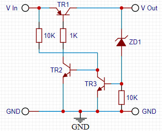
It works on the basis that as the output voltage increases to the point that the Zener diode conducts, the voltage at the base of NPN transistor TR3 increases and as it approaches 0.7 Volts it begins to turn-on. As it does this, it clamps the base voltage of the other NPN transistor, TR2, which turns-off and in the process reduces the current flowing into the base of the PNP transistor TR1 which also turns off reducing the current flowing through it, and thereby lowering the circuit's output voltage (and vice versa for a decrease in output voltage). The output voltage of the regulator is therefore set by the voltage of the Zener diode, ZD1, plus the turn-on voltage of transistor TR3. The reason that this is a low dropout regulator is that the dropout is determined only by the minimum collector-emitter voltage of the PNP transistor, TR1, when it is turned fully on, and this can be as low as 0.2 Volts. The primary issue with this circuit is that its ability to regulate the output voltage is based partially on the turn-on voltage at the base of TR3 and all bipolar transistors are very prone to changes in their turn-on voltage with temperature.
In addition, Zener diodes do not come in every possible Voltage (the nearest you could get to give a 10 Volt output would be to use a 9.1V Zener which together with the turn-on voltage of the transistor of about 0.7 Volts would yield a 9.8 Volt output). Zener diodes are also, like the junction in a bipolar transistor, prone to temperature drift. Thus, what might be a perfect 9.8 Volt output at room temperature might drop to 9.6 Volts at 50C or 10 Volts at -10C - not particularly well regulated.
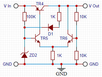
An alternative design (shown above) uses a 'long-tailed pair' (TR5 and TR6) and also uses a Zener diode to provide the voltage reference. Zener diodes of values around 6 Volts have virtually constant temperature characteristics meaning that if used as the voltage reference in a regulator, the output will vary very little as it heats up or cools down. Zener diodes typically need about 5mA of current passing through them to achieve a stable reference voltage and this can be provided from the regulated supply (through D1 and the 1K resistor), ensuring a near constant reference voltage.
The long-tailed pair basically function as an inverter: What one transistor does, the other does the opposite. So if the current in one transistor increases, the current in the other one decreases. The base of NPN transistor TR5 is provide with a fixed voltage reference by the Zener diode, whilst the base of the other senses the output voltage of the circuit via the potential divider made up of the two 10K resistors. The circuit will try and balance the voltage at both bases as follows: If the output voltage decreases, transistor TR6 will draw less current (as its base voltage decreases) and by dint transistor TR5 will draw more current, which forces more current into the base of the PNP transistor, TR4, which will conduct more heavily and increase the output voltage and behold the output voltage is stabilised.
As with a variable regulator, the output voltage can be adjusted by changing the value of the two 10K resistors. As it sits, the output voltage would be exactly 2 times the voltage across the Zener diode. The 100K resistor, by the way, is to provide some initial current for the Zener diode; otherwise, when the circuit is initialised, the Zener voltage and output voltage would both be zero and the circuit would be in equilibrium and nothing else would happen.
This may seem a silly length to go to to produce a low dropout regulator when off-the-shelf ones are available, but oddly, the design using discrete components takes up little more space on a circuit board, performs just as well, and is cheaper. It is also surprisingly good at getting rid of supply hum, buzz, ripple and noise. In addition, if the diode in the circuit (D1) is replaced by a light emitting one (an LED) it will provide an indication that all is well with the regulated output: your off-the-shelf regulator doesn't do that for you now does it?
Comments