How not to design transmitters and receivers: part 17 (PCB and kit)
There seems to have been a lot of interest in the Wireless Waffle series entitled 'How Not to Design Transmitters and Receivers'. One or two (or, indeed, a few more) people have asked about a printed circuit board (PCB) layout and even whether it might be possible to put a kit of parts and set of instructions together for experimenters who wanted to try and build a 1 Watt FM transmitter/exciter for themselves. In that vein, a PCB has been designed for a simple synthesised PLL transmitter which has the following characteristics. It:
There are no surface-mount parts on the PCBs, making it easy to assemble even for the relatively cack-handed, and the ICs can be socketted for those not confident enough to solder the chips directly to the board. The only complexity is that there are a number of coils to be manually wound, including one on a small toroid.
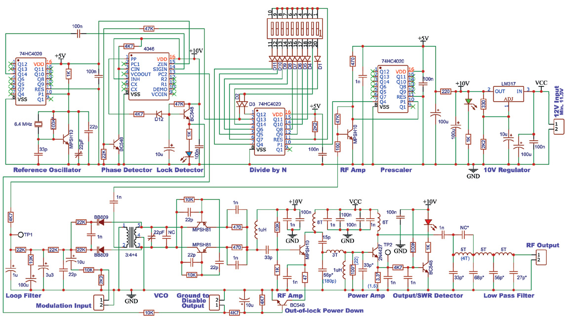
The circuit diagram is below and those who have followed the series will recognise the various elements which go together to make up the overall design.
Three options are available for anyone who wishes to have a go a building this design:
To get hold of your FM 3.05K kit, please leave a postcard with your name and address, together with £10,000 in unmarked £20 notes in a rucksack in a dustbin of your choice at Piccadilly railway station in Manchester at 23:15 any sunny Tuesday night in March.
Alternatively, fill in the contact form, stating which version of the kit you wish to purchase, and where it needs posting to, and we'll get back to you with a final price (including the postage) and how to pay (this will be via PayPal).
- Uses a half-frequency oscillator, to get round the feedback problems that an at-frequency oscillator can suffer from in RF hot environments
- Is built from the minimum sub-set of components, to keep the cost of getting all the parts together as low as possible
- Doesn't use lots of obsolete, expensive or difficult-to-get-hold-of parts
- Can accommodate different output transistors (such as the 2N4427, MRF237 and similar)
- Can use a range of transistors for most of the parts (such as the BF199, MPSH10 and similar)
- Will produce around 1 Watt across the band with as little fiddling as possible (or more depending on the output transistor)
- Has an output that is legally clean enough to either be connected directly to an antenna, or amplified to high power (nothing over 60dB below the carrier)
- Keeps the digital and analogue parts of the circuit as seperate as possible to minimise digital noise on the modulation
- Doesn't require any micro-controllers and thus does not require any software to be written/blown
- Has out-of-lock power-down to stop transmissions on unwanted frequencies whilst the phase lock loop is settling down
- Is straightforward to set onto the desired frequency
- Can be easily tested and maintained (to the extent that it could be built in stages, testing each along the way)
- Has a flat modulation frequency response from around 3 Hz to at least 100 kHz, providing superlative audio
- Does not need any tuning (other than setting the VCO frequency)
- Can have its output quickly disabled (i.e. for connection to a high SWR detector)
- With some component changes, can be made to work on Band-I too (the final design will work down to about 52 MHz)
There are no surface-mount parts on the PCBs, making it easy to assemble even for the relatively cack-handed, and the ICs can be socketted for those not confident enough to solder the chips directly to the board. The only complexity is that there are a number of coils to be manually wound, including one on a small toroid.
The circuit diagram is below and those who have followed the series will recognise the various elements which go together to make up the overall design.
;)
Three options are available for anyone who wishes to have a go a building this design:
- PBC's for this project are available on their own for those who wish to assemble the various components required themselves, or who have a large junk-box full of suitable components. This is £4.99 plus postage.
- In addition, a minimalist kit is available which contains the PCB, as well as the ICs, transistors and the toroid and wire for winding the coils as these are the parts least likely to be in a typical junk box. This is £24.99 plus postage.
- Finally, a full kit of parts is available including the PCB, semi-conductors, toroids and all the resistors, capacitors and diodes needed to complete the project. This is £34.99 plus postage.
To get hold of your FM 3.05K kit, please leave a postcard with your name and address, together with £10,000 in unmarked £20 notes in a rucksack in a dustbin of your choice at Piccadilly railway station in Manchester at 23:15 any sunny Tuesday night in March.
Alternatively, fill in the contact form, stating which version of the kit you wish to purchase, and where it needs posting to, and we'll get back to you with a final price (including the postage) and how to pay (this will be via PayPal).
Comments