
How not to design transmitters and receivers (part 1: voltage controlled oscillators)
Saturday 5 June, 2021, 12:20 - Amateur Radio, Broadcasting, Licensed, Pirate/Clandestine, Electronics, Radio Randomness
Posted by Administrator
Posted by Administrator
 Hasn't lockdown been a bore? There is only so much Netflix or Amazon Prime that it's possible to watch, let alone enjoy. Mind you, having said that, and if you haven't already seen it, Halt And Catch Fire is a must-watch for any kind of nerd or geek who remembers the dodgy, unreliable and overheating computer designs of the early 1980s.
In order to maintain some kind of sanity, in the Wireless Waffle workshop work has been proceeding on the crudely conceived idea of an instrument that will not only supply emissions for use in radio transmissions, but one which would also be capable of receiving them. Or to put it simply, a wideband VHF transmitter and a matching receiver which could be used as an audio link. Having designed and built many of these devices back in the 1990s, it ought to have been relatively straightforward to revisit those designs and modernise them. Alas, RF design is a fickle mistress and in addition to resulting in some truly awful designs, some very nice ones have also emerged. Along the way, many topics have had to be re-learnt all of which makes for some (very techy) content for a series of blog posts which may, in some small way, help those who might seek to replicate this pointless pass-time.
As Julio Iglesias once said, let's Begin (at) The Beg(u)in(e)(ning). There are dozens of designs for simple VHF variable frequency oscillators (VCO) on the internet, so getting something to generate the intial signals ought to be relatively straightforward. However, there is also lots of evidence to suggest that in cases where signals from oscillators are amplified to high power levels, and sent through antennas which are relatively close to the transmitter, radio frequency (RF) feedback can occur causing buzz and hum to the transmitted signal. The way around this is to have the oscillator work on a different frequency to the one being transmitted.
This might seem like an odd thing to do, however it is not uncommon. Two primary methods are used to achieve this:
- A variable oscillator is mixed with a fixed oscillator and the sum (or difference) of the two is then filtered and amplified. For example, a variable oscillator covering 100 to 125 MHz could be mixed with a fixed oscillator at 75 MHz, resulting in outputs either at 175 to 200 MHz (if the two signals are added) or 25 to 50 MHz (if the two are subtracted). The difficulty with this approach is that mixers are, almost by necessity, non-linear devices. In the first case, with the oscillator on 100 MHz, and the wanted output on 175 MHz, the second harmonic of the oscillator would fall at 200 MHz which, being within the 'wanted' output range, could not easily be filtered out. Careful selection of the variable and fixed frequencies can help overcome this, however this limits the possible range of output frequencies and also requires lots of filtering which is fine if the wanted frequency range is relatively narrow, but more difficult if the frequency range is wider.
- The varible oscillator operates at a frequency which is a sub-harmonic of the wanted frequency, and a multiplier is then used to double, triple or multiply the frequency by even higher orders. If we therefore wanted an output from 25 to 50 MHz, we could, for example, use an oscillator running from 8.33 to 16.66 MHz and triple it. Once again, multipliers are also non-linear devices and the 16.66 MHz signal would also be doubled to 33.33 MHz, which being within the wanted output frequency range would also be difficult to filter out. This method therefore is not without its problems and also requires filtering with all the issues associated with that.
Digging around the internet for 'Kalitron' circuits in which the double frequency (or '2f') output is available, yielded very few results. An article entitled, High Frequency VCO Design and Schematics by Iulian Rosu did discuss a Differential Cross-Coupled VCO and though Iulian's design is meant for very high frequencies, his article does provide some useful guidance. One of these is that the transistors should ideally be biased at the point between their saturation and linear regions (i.e. almost fully turned on). It was therefore decided to try and adopt this circuit.
Since getting involved in designing radio equipment in the 90s, the use of PNP transistors for oscillators has always been the preferred Wireless Waffle approach. The primary benefit of this is that the inductor used to set the frequency of the oscillator is grounded, making applying some kind of variable capacitance across it far easier. And so experimentation began. It would have been easy to copy the Veronica approach, however this requires 6 individual coils to be wound, and finding a simpler way to achieve the same results was sought. Getting such an oscillator to work was not difficult, but finding the correct balance of transistor current and bias, and then tapping off the doubled frequency component with sufficient 'oomph' to do something useful with, whilst not disturbing the oscillator's stability proved a complex balancing act. In addition, to keep the costs of the associated (and yet to be designed) phase locked loop (PLL) down by using off-the-shelf high speed CMOS chips also required a method to extract the un-doubled output to be found.
The final design works. Actually, that was meant to be the start of a sentence, but having got as far as 'the final design works', seemed sufficient.
;) An inductor wound on a toroidal core was used for the oscillator, with a secondary winding (not shown in the picture) used to tap off the un-doubled output. This is somewhat fiddly to wind, but with practice becomes much easier and is the alternative to winding the 6 coils used in the Veronica design.
An inductor wound on a toroidal core was used for the oscillator, with a secondary winding (not shown in the picture) used to tap off the un-doubled output. This is somewhat fiddly to wind, but with practice becomes much easier and is the alternative to winding the 6 coils used in the Veronica design.Once oscillating a new issue was identified: the varicap diodes being used to tune the circuit were rectifying the RF generated by the circuit causing mountains of unwanted non-linear signals to be generated. This was partially fixed by not connecting the varicaps directly together but by short-circuiting them at RF with a capacitor whilst driving the DC level through separate resistors. Keeping the drive voltage above around 4 Volts keeps the diodes in their non-rectifying, more linear region though slightly reducing the potential tuning range. Reducing the amplitude of the oscillations would solve this a little but also reduce the potential output power. RF design is nothing if not a set of complicated compromises.
The doubled output from the oscillator is around 10 dBm (10 milliWatts) which is not quite enough to immediately drive a power amplifier to a reasonable level, so a buffer will be needed. The addition of a buffer will add (at a later date) the option to implement an 'out of lock power down' function in which the output of the transmitter is switched off until it has settled on the required frequency, without which a multitude of problems can occur.
The final circuit (or 'schematic' in American English) of the voltage controlled frequency-doubling oscillator (or 'uppy-downy-frequency-makey-matey' in Australian English) is shown below. Layout should be kept as symmetric as possible to minimise the amount of 'f' which is present on the '2f' output. The transistors used were originally type BF451 which are ideal for the task but other PNP RF transistors such as the BF509, BF939 or MPSH81 would work equally well.
;)
Future articles in this series may explore other unbelievably exciting topics such as:
- how not to blow up RF power transistors
- how well soldering irons burn things like skin and phone covers
- why 40 year old transistors trump modern ones
- glaringly obvious mistakes to make when sending PCBs for production
- forgetting that receivers are sensitive devices
- badly matching one stage to another
- getting PLL loop filters to oscillate wildly
- and much, much less...
add comment
( 237 views )
| permalink
| 
 ( 3.1 / 476 )
( 3.1 / 476 )
Squeezing the life out of Pirates
 Back in 2008, Wireless Waffle discussed the fact that the licensing of new community radio stations by Ofcom had forced many pirate radio stations to change frequency and in some cases to move to using two (or more) frequencies simultaneously in order to provide wide area coverage without treading on the toes of officially licensed stations.
 As the number of community stations continues to grow, the problem of finding a 'clear' frequency for the pirates to operate on becomes increasingly difficult. Indeed, one might even go so far as to suggest that part of the reason for Ofcom's relatively newly found interest in licensing community radio stations is to purposefully force pirates off the airwaves, which would, of course, be in perfect alignment with their objectives as the regulator of the radio spectrum.
For many years Ofcom claimed that there were no FM frequencies available for new radio stations as the band was full, but over the past 10 years or so, they have licensed dozens of community stations all over the country. Being lower power and covering a smaller area they have managed to squeeze a number of stations into a band which had been previously claimed to have no space in it. What is interesting is how similar the frequencies chosen by Ofcom for the community stations are to those that were previously employed by the pirates themselves, suggesting that the frequencies that the pirates were using were well chosen so as to try and avoid causing interference to legitimate stations.
Take, for example, the handful of radio pirates operating in Brighton on the south coast of the UK. The table below shows some of the frequencies used by pirates in the area, and the frequencies used by the four community stations now broadcasting to the city. You will note that there is a large degree of commonality.
| Pirate�Station | �Frequency� | Community�Station | �Frequency� |
|---|---|---|---|
| InFront FM Haven976 | 97.9 97.6 | Gaydio | 97.8 |
| Radio 4A | 101.4 | 1BTN | 101.4 |
| CodeSouth FM | 105.6 | Platform B | 105.5 |
| - | - | Radio Reverb | 97.2 |
;) One station, CodeSouth, has changed frequency four times since it first went on air in 2012. Initialy on 108.0, it moved to 88.8 in 2013, then to 98.5 (the frequency previously used by another Brighton pirate 'FIP') from 2014 to 2015, then to 105.6 until late 2018 and is currently on 88.2 MHz. Incidentally, the choice of 88.2 MHz may not be the best, as it is the frequency used by a low-power relay of BBC Radio 2 in nearby Bexhill. Though the relay does not put a strong signal into Brighton and thus the frequency may appear empty, the same may not be true of CodeSouth's big signal heading in the opposite direction (88.0 may have been a better choice). Of course there are a decreasing number of frequencies available and any choice is likely to cause potential interference to someone.
One station, CodeSouth, has changed frequency four times since it first went on air in 2012. Initialy on 108.0, it moved to 88.8 in 2013, then to 98.5 (the frequency previously used by another Brighton pirate 'FIP') from 2014 to 2015, then to 105.6 until late 2018 and is currently on 88.2 MHz. Incidentally, the choice of 88.2 MHz may not be the best, as it is the frequency used by a low-power relay of BBC Radio 2 in nearby Bexhill. Though the relay does not put a strong signal into Brighton and thus the frequency may appear empty, the same may not be true of CodeSouth's big signal heading in the opposite direction (88.0 may have been a better choice). Of course there are a decreasing number of frequencies available and any choice is likely to cause potential interference to someone. The other pirate stations have not been heard of for some time. It seems at least partially feasible that some of the presenters have found their way onto one of the new community stations and as such there is no longer a need for them to fly the jolly radio roger. In this respect, it could be argued that Ofcom's community radio policy has had a double whammy effect and both taken away the frequencies from the pirates, and taken away the needs of the DJ's to use pirate stations as an outlet for their music.
 Despite all the above, the simplicity of Internet streaming (which many of the pirates also do) and the opportunity of space on local DAB multiplexes, the UK's licensing laws must still be failing some part of the musical community, otherwise there would no longer be a need for the pirates. The whole situation sounds hugely reminiscent of the very early days of the pirates, when the BBC launched Radio 1 to try and take away the need for the offshore stations playing 'pop' music, yet the pirates persevered. What will it take to finally find a way to end unlicensed broadcasting, and give everyone who wishes to have a radio show the audience they seek?
Radio Caroline 648 kHz
Wednesday 22 November, 2017, 15:31 - Broadcasting, Licensed, Pirate/Clandestine
Posted by Administrator
Posted by Administrator
 Wireless Waffle previously sang the praises of the boat trips to visit the Ross Revenge, the home of former radio pirate, Radio Caroline. We also noted that they had been awarded a licence to operate a 1 kiloWatt transmitter on 648 kHz in the Suffolk and north Essex area.
Well, it seems the engineering bods on the east coast have managed to get it together, and recently test transmissions on 648 kHz were spotted by a number of listeners, such as a DXer in Humberside who posted the video below on YouTube.
Though you may not be able to interpret the waterfall display shown on the video, what you see is the Radio Caroline signal in the middle. The two bright lines either side represent radio stations on the adjacent frequencies (639 and 657 kHz respectively). Normally, for AM broadcasting, each station would be allowed to occupy half of the bandwidth between its assigned frequency and the adjacent channels, meaining that it would extend +/- 4.5 kHz either side of its centre frequency. It is this limitation they gives medium and long wave broadcasting their characteristic 'muddy' sound, as the limitation in spectrum also restricts the amount of audio bandwidth that can be transmitted.
It's therefore notable that the Radio Caroline transmission on 648 kHz extends far closer to the adjacent frequencies than 4.5 kHz. It appears closer to +/- 6.5 kHz wide (or maybe even more). This would allow the station to transmit a wider audio bandwidth and thus sound a little 'brighter' on-air. Such derogations from the norm are not unusual as the medium wave band has become emptier, as there is more space for stations to spread out and sound better.
As an example, the three audio clips below have been filtered with different bandwidths. Just click on the relevant button to hear the difference (note that this doesn't work in all browsers.
| Audio�Bandwidth | Play |
|---|---|
| 15 kHz, stereo (FM Stereo) | |
| 6.5 kHz, mono (extended bandwidth AM) | |
| 4.5 kHz, mono (standard bandwidth AM) |
 Given that of the neighbouring frequencies, the nearest stations on 639 kHz are in the Czech Republic and Spain (previously crowned the queen of medium-wave broadcasting) and on 657 kHz in Spain (again) and North Wales, it seems unlikely that the additional bandwidth being used by Radio Caroline will give any problems and we are sure that listeners will enjoy the cleaner, brighter sound that they will have on-air.
Ross Revenge Boat Trips
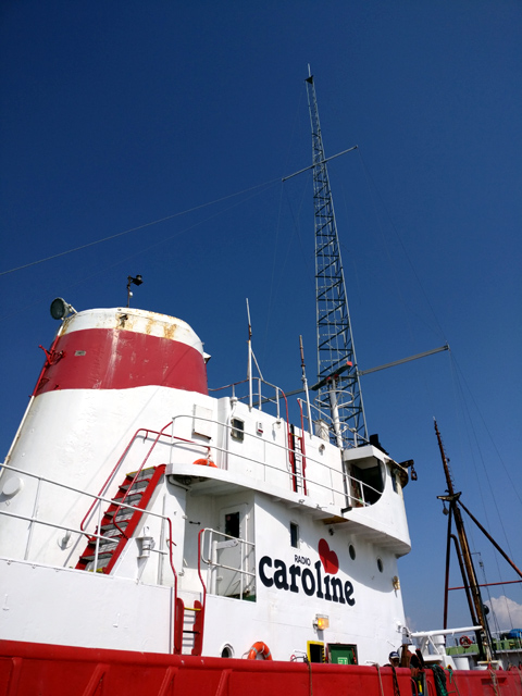
Wireless Waffle recently spotted that boat trips to see Radio Caroline's ship, the Ross Revenge, were available to book from their web-site (follow the link) and so it seemed like the perfect opportunity to don an anorak and set sail. On the day of the visit, the weather was beautiful, sunny, 26C and the sea was calm, but it isn't always like that. Boarding the Razorbill 3 , the tender which takes you from the jetty at West Mersea out to the Ross Revenge, it was a pleasure to see so many families taking advantage of the weather to go crabbing. The ride out took about 25 minutes and was a delight in itself with the cool sea air rushing past.
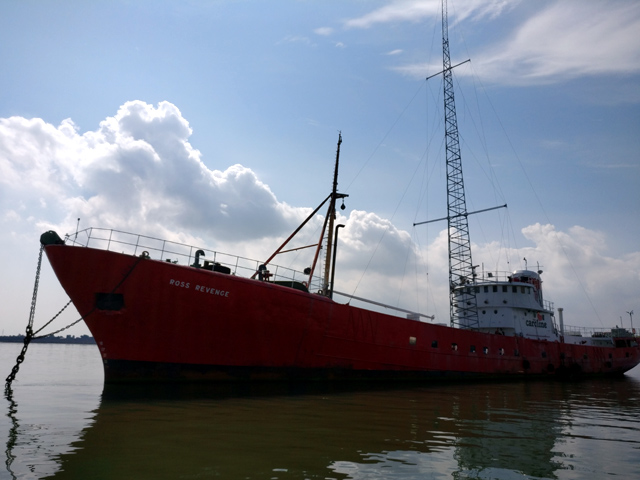 Pulling alongside the boat, it looked exactly as it does in all the postcards, though the current mast is a lot smaller than the 100 metre mast that was in use for transmission during Radio Caroline's heyday. Arrival onto the boat was greeted by a cup of tea and a fig roll in the mess and a description of the history of the boat, which turns out to have been a prize Grimsby-based fishing boat originally made as an Icelandic ice-breaker. Much of the tour of the boat is about the Ross Revenge itself, as well as the catastrophic events of October 1987 which saw the original mast collapse in a storm.
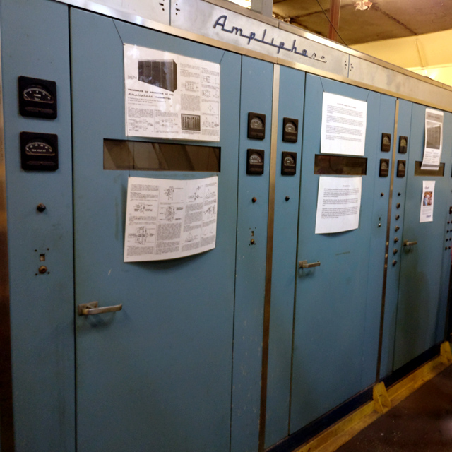 Of course no tour of such an historic ship would be complete without a visit to the studios and the technical facilities such as the engine room, generator room and of course the transmitter room. The 50 kW 'Ampliphase' transmitter consumed nearly 1 tonne of fuel per day to operate so it's no wonder that getting supplies to the boat, including diesel and fresh water, were so critical.
Though the notion of being a pirate at sea may seem romantic, it is clear that the lives of the DJs and other staff must, at times, have been pretty miserable. The cabins below the deck are relatively spartan and if it was blowing a gale, there couldn't have been much to do if you weren't on air.
 The return from the ship to the shore was equally exhilarating and you left with a lot of respect for those who took to the seas to try and deliver a radio service that filled the gap left by the legal, land-based services.
The tour comes with the Wireless Waffle 'big thumbs up' seal of approval, and is highly recommended. Obviously the weather can not be guaranteed, but an interesting and enlightening day-out is assured.
Recently, Radio Caroline has been awarded a licence by Ofcom to operate a 1 kW medium wave service on the old BBC World Service channel of 648 kHz. Whether the station can hold its own in today's crowded, on-line, market remains to be seen, but there will no doubt be a few anoraks tuning in for old time's sake. And maybe they can re-capture the spirit of those halcyon days without needing sea sick buckets.
;) Pulling alongside the boat, it looked exactly as it does in all the postcards, though the current mast is a lot smaller than the 100 metre mast that was in use for transmission during Radio Caroline's heyday. Arrival onto the boat was greeted by a cup of tea and a fig roll in the mess and a description of the history of the boat, which turns out to have been a prize Grimsby-based fishing boat originally made as an Icelandic ice-breaker. Much of the tour of the boat is about the Ross Revenge itself, as well as the catastrophic events of October 1987 which saw the original mast collapse in a storm.
Pulling alongside the boat, it looked exactly as it does in all the postcards, though the current mast is a lot smaller than the 100 metre mast that was in use for transmission during Radio Caroline's heyday. Arrival onto the boat was greeted by a cup of tea and a fig roll in the mess and a description of the history of the boat, which turns out to have been a prize Grimsby-based fishing boat originally made as an Icelandic ice-breaker. Much of the tour of the boat is about the Ross Revenge itself, as well as the catastrophic events of October 1987 which saw the original mast collapse in a storm. ;) Of course no tour of such an historic ship would be complete without a visit to the studios and the technical facilities such as the engine room, generator room and of course the transmitter room. The 50 kW 'Ampliphase' transmitter consumed nearly 1 tonne of fuel per day to operate so it's no wonder that getting supplies to the boat, including diesel and fresh water, were so critical.
Of course no tour of such an historic ship would be complete without a visit to the studios and the technical facilities such as the engine room, generator room and of course the transmitter room. The 50 kW 'Ampliphase' transmitter consumed nearly 1 tonne of fuel per day to operate so it's no wonder that getting supplies to the boat, including diesel and fresh water, were so critical.Though the notion of being a pirate at sea may seem romantic, it is clear that the lives of the DJs and other staff must, at times, have been pretty miserable. The cabins below the deck are relatively spartan and if it was blowing a gale, there couldn't have been much to do if you weren't on air.
;) The return from the ship to the shore was equally exhilarating and you left with a lot of respect for those who took to the seas to try and deliver a radio service that filled the gap left by the legal, land-based services.
The return from the ship to the shore was equally exhilarating and you left with a lot of respect for those who took to the seas to try and deliver a radio service that filled the gap left by the legal, land-based services.The tour comes with the Wireless Waffle 'big thumbs up' seal of approval, and is highly recommended. Obviously the weather can not be guaranteed, but an interesting and enlightening day-out is assured.
Recently, Radio Caroline has been awarded a licence by Ofcom to operate a 1 kW medium wave service on the old BBC World Service channel of 648 kHz. Whether the station can hold its own in today's crowded, on-line, market remains to be seen, but there will no doubt be a few anoraks tuning in for old time's sake. And maybe they can re-capture the spirit of those halcyon days without needing sea sick buckets.