
How not to design transmitters and receivers: part 18 (IF amplifier)
Friday 24 June, 2022, 07:37 - Broadcasting, Licensed, Pirate/Clandestine, Electronics
Posted by Administrator
Next in the series of 'How not to design transmitters and receivers' we shall tackle the intermediate (IF) amplifier. This seemingly innocent little circuit is teeming with complexity and getting it right is not straightforward.Posted by Administrator
According to the calculations made in Part 15 of this series, the IF amplifier requires a gain of 19 dB or thereabouts (a few dB or so either way will not make too much difference). In addition, it needs to have an input and output impedance of 330 Ohms. This means that any ceramic filter used in the IF could be placed either before, or after, the amplifier and be correctly matched (or indeed two filters could be used). It is the combination of achieving a 330 Ohm input and output impedance, together with the requisite gain that makes the circuit more complex.
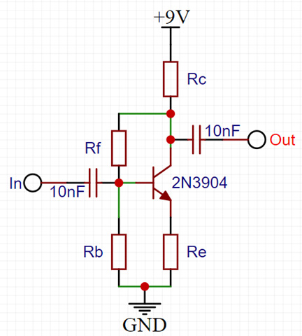
We shall use the circuit above as the basis for our amplifier. This is an untuned amplifier and will therefore provide gain across a wide range of frequencies which can sometimes cause problems as it will amplify both wanted and unwanted signals, however this has the major advantage that no tuning is required.
The gain of the circuit is primarily set by the ratio of Rc and Re, with gain being calculated as Rc divided by Re. However it needs to be remembered that Rc is in parallel with the load connected to the output, and that the transistor has an internal resistance in series with Re whose value is determined by the current flowing through the transistor (usually defined as 26 divided by the transistor emitter current (Ie in milliAmps).
Taking all this into account, the gain of the circuit can be (roughly) calculated by the equation:
Rc*Rload
(Rc+Rload)*(Re+26/Ie)
The input impedance of the circuit comprises three different values in parallel:
- Rb which is directly across the input of the circuit;
- The impedance of the emitter resistor Re (including the transistor's internal resistance) multiplied by the gain of the transistor (the Beta or hfe); and
- The impedance of the feedback resistor Rf divided by the gain of the transistor circuit (not the gain of the transitor itself).
1
1/Rb+1/(hfe*(Re+26/Ie))+1/(Rf/gaincircuit)
Rc*(Vcc-Rc*Ie)
Vcc
One final consideration is the transistor bias. Ideally, the output of the transistor would be set to have a voltage roughly half of that of the supply (give or take). This ensures that the output of the amplifier can swing up and down as far as possible before 'hitting the rails' and no longer amplifying. The output voltage (at the transistor's collector) is determined by Rc and the current passing through the transistor. The current passing through the transistor is determined by the current flowing into the base of the transistor multiplied by its gain. In the case where the bias current is set through the feedback resistor from the collector (Rf), this calculation is iterative, as the base current is then related to the collector current.
Another kink is that the collector current can also impact the gain of the transistor, with very low collector currents reducing the gain. Similarly, currents too high can have similar effects. It is necessary to consult the datasheet for the transistor being used to determine how the current affects the gain. Usually over a relatively wide range, the gain will be roughly constant (and be at its highest) and this is often the point that should be aimed for.
Hopefully, by now, you can see why getting the various resistor values correct is complicated, and how changing one value (such as the emitter resistor, or feedback resistor) can change the gain and impedances of the circuit.
The following values therefore produce an amplifier which meets, so far as is possible, all the criteria which are required for the IF gain stage:
- Rb = 2.2K Ohms
- Rc = 560 Ohms
- Re = 8.2 Ohms
- Rf = 10K Ohms
- The voltage gain of the amplifier is 17.8 (or 25 dB) before the reduction in gain caused by the feedback resistor Rf is taken into account;
- The input impedance of the amplifier is 331 Ohms;
- The output impedance of the amplifier is 299 Ohms.
Another set of values which yields the correct input and output impedances is:
- Rb = 1K Ohms
- Rc = 470 Ohms
- Re = 22 Ohms
- Rf = 4.7K Ohms
Note that in reality there are various additional factors which will impact the performance of the circuit, especially at radio frequencies. In particular, various capacitances within the transistor will tend to limit the high frequency performance. Choosing a transistor whose transition frequency (ft - the frequency at which the transistor's gain drops to unity) is significantly above the required amplifier frequency minimises these issues. According to its datasheet, the 2N3904 used in the amplifier has an (ft) of 300 MHz, and as we want the amplifier to operate at 10.7 MHz, this is sufficient margin to largely ignore these other factors.
add comment
( 3354 views )
| permalink
| 
 ( 3.1 / 1271 )
( 3.1 / 1271 )