Friday 9 February, 2007, 16:06 - Amateur Radio
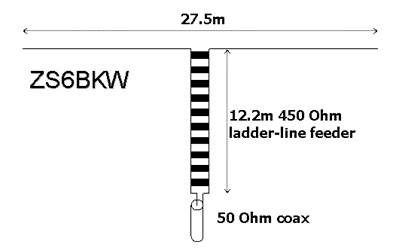
So having whet your appetite with details of the ZS6BKW multi-band antenna, I've finally finished my own installation of the antenna and will share my findings with you. The good thing about this particular multi-band antenna is that it covers the majority of the HF amateur bands that I'm interested in, particularly 80m, 40m, 17m and 12m, as well as 20m. 10m coverage (and 80m for that matter) is a bit poor.The original design shows two wires of 14.2 metres fed with 11.1m of 300 Ohm twin-feeder. However having scouted around the internet, I discovered that there is a revised version using 450 Ohm ladder-line feeder (which seems to be as easily if not more easily available than the 300 Ohm stuff). It has the main advantage that it's marginally smaller which, given the rather small size of my back garden meant that it should just squeeze into the available space.
One element of the original design that seems odd is the suggestion that no balun is needed at connection between the twin-feeder and the coax cable. Fundamentally, twin-feeder is a balanced system and coax is an unbalanced system and any radio (or audio) engineer will tell you that connecting one to the other is a recipe for disaster. In the case of radio systems, the upshot is usually that RF radiates from the outer of the coax increasing the potential for RFI and picking up more interference from neighbouring electrical devices (computers etc).
I managed to get a pole on the back of the house, the top of which is about 30ft (10m) above ground level and stretched the necessary 13.75m of copper wire (uncoated) from the pole to the two corners of the back garden which just fits. The whole installation is in the form of a sloping inverted-V with each end probably no more than about 12ft (4m) above ground level. The 450 Ohm ladder line is fastened along the soffit board, runs down the back of a plastic drain pipe and then along a wall until it meets the 50 Ohm coax - not straight or vertical or perpendicular to the antenna in any way. At this point, the coax (RG-58U which is sufficient as the run is so short) is wound 8 times through a iron powder ferrite to form a choke balun. A run of less than 10m of coax then terminates in the shack.
Like all experimenters, I cut both the wire (13.8m) and the ladder line (12.3m) slightly too long to allow for tweaking later. My first assembly resonated on 6.86, 13.76, 17.64 and 24.15 MHz (and less well on 3.4 and 28.44 MHz too) - on average about 4% low in frequency. The original ZS6BKW article does mention that installed in an inverted-V configuration, resonances would be a little low.
After reducing the length of the ladder line to the design figure of 12.2m and tweaking the length of the wires, ending up at 13.5m, the antenna now resonates beautifully on 7.1, 14.11, 18.06 and 24.8 MHz. On each of these frequencies, the SWR is below 1.3:1 indicating a pretty good match. There are also dips in SWR at 3.55 MHz (SWR 5:1) and 29.02 MHz (2:1) and, usefully, at 50.84 MHz (3:1) meaning I can also use the antenna on 6m too with a bit of a tweak of a tuning unit.
I haven't had the antenna in place long enough to determine its DX potential yet, but stations over 5000km away are readily audible. Having searched the net for articles on this antenna, I found very few so I thought documenting my experience might help others. Let me know how you get on.
3 comments
( 7516 views )
| permalink
| 


 ( 3 / 13814 )


 ( 3 / 13814 )
Wednesday 10 January, 2007, 13:37 - Amateur Radio
I make no real apology for the blatant plagiarism here. Following my comments back in September 2006 on All Band Antennas for Skinflints, I've been trying to find the original article relating to the ZS6BKW antenna as I fancied making one. Nowhere could I find the article on-line but I did manage to get a friend to scan in the article from the original Radio ZS publication in 1985. I'll document in a future blog my experiences of getting this fascinating idea of an antenna built and to work as well as providing details of the different variants which I've found scattered around the net, but for now, here's the text of the original article:
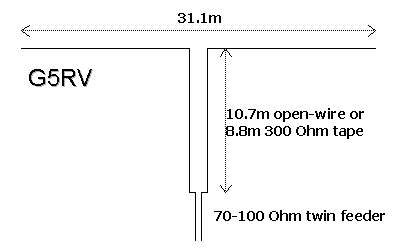
The July 1958 edition of the RSGB Bulletin contained an article by Louis Varney G5RV on a novel multiband dipole which did not require traps. Figure 1 (below) shows the antenna, later to become known universally as the ‘G5RV’.
Like so many good ideas it is so simple. It works as follows: On 20m the flat-top is three halfwaves long. Its feedpoint impedance is therefore low and because the open-wire line is one half-wave length on that band it merely transfers that low impedance to its other end and there presents a reasonable match to the ‘Twin’ feeder on the rig. On 40m the feedpoint impedance is very high (and inductive) because the antenna is now three quarters of a wavelength, but the transmission line transformer is now one quarter-wavelength and so functions as a quarter-wave transformer. Hence the high value of the load impedance, Z(L), is transformed into a much lower value, Z(IN), by the well-known relationship for the quarter-wave transformer:
Z(IN)=Z(O)²/Z(L)
Where Z(O) is the characteristic impedance of the open-wire line, typically 300-600 Ohms. It is rather like an automatic ATU hanging off the antenna! On 15m and 10m the antenna/feedline combination were again said to combine to present reasonable impedances to the twin-feeder, which was all that a valve power amplifier with link or pi-coupling ever requires. The tubes of that era coped far better with mismatches than do the solid-state devices of today!
On reflection, it soon became apparent that one should be able to improve on the performance of this antenna by using a computer to optimise the length of the flat-top and matching transformer such that the impedance presented at the transmitter end of the line more closely matches the 50 Ohms, plus or minus a few, that our modern finals will tolerate.
To do this we need to know the feedpoint impedance of a centre-fed dipole antenna as we change its length and as we change the frequency. This can be calculated but it by no means an easy task and a far simpler approach (and one that is probably more reliable) is to use the data which is available in the professional literature. Professor R W P King at Harvard University had fortunately provided us with this information in tabular form. To use it requires only that it be stored in a ‘look-up’ table in the computer. Given the frequency and the length of the antenna, we then have its impedance.
The next step was to consider the role of the transmission line transformer. How long should it really be and is one value of Z(O) better than another? Without going into any detail here suffice it to say that Louis Varney’s statement, way back in 1958, that Z(O) was not too critical is in fact not far off the mark. It has been shown that there is a broad peak of Z(O) values from about 275 Ohms to 400 Ohms, which will work adequately. This means that either homemade open-wire line or commercial 300 Ohm tale could be used. Do choose the best quality 300 Ohm tape though because that sold for FM-band folded dipoles doesn’t really weather at all well.
To determine the length of the matching section we use the standard transmission line equation which gives us Z(IN) if we know Z(L) and Z(O), the frequency and the length of that line. By re-arranging the equation we can find the length at any given frequency and Z(O) once we’ve used the ‘look up’ table to find Z(L). Of course Z(IN) is fixed by the required standing wave ratio on the 50 Ohm cable to the rig. Usually this VSWR may not be more than 2:1, and is always specified by the transceiver manufacturer.
Armed with this information writing the computer program is a fairly conventional procedure and will not be described here. Ideally a single antenna should operate on all the HF bands from 160 through to 10m. That is a tall order though so we would probably settle for a compromise of say five of the nine bands (including the three new ones.) Having chosen that number we then instruct the computer to change the flat-top length, the length of the matching section and Z(O) until it finds that combination of the three parameters which yield better than 2:1 VSWR on at least five bands. Clearly this involved an iterative or ‘going around the loop’ procedure and can take a fair amount of computer time, but the results are worth the effort.
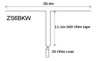
In Figure 2 (above) are the details of the improved, computer-designed, G5RV. You will notice that the flat-top is shorter than Varney’s and that the matching section is longer. A velocity factor of 0.85 was used for the 300 Ohm tape. Particularly important is the fact that this new antenna is designed for use with 50 Ohm cable and not the 70-100 Ohm twin of 1958. No balun is specified simply because neither the theory nor considerable experimentation justified the inclusion of one. Simply interconnect the 300 Ohm tape and the 50 Ohm coax, taking the normal precautions to keep moisture out.
Both in theory, from the computer predictions, and in practise, when erected horizontally at a height of 13m, the antenna provides an acceptable match on the 7, 14, 18, 24 and 28 MHz bands. The original G5RV was tested by way of comparison (both with the computer and in the field) and found to be far less effective. Only the 14 and 24 MHz bands produced standing wave ratios of less than 2:1 when fed with 75 Ohm cable, as designed.
The new antenna was also tested in the very popular inverted-V configuration and the results showed, not unexpectedly, that the frequency on each band at which the best match occurred were all shifted somewhat lower, but the same general characteristics as discussed above for the horizontal configuration still applied. Likewise, changing the height above ground from 7 to 13m did not markedly change the situation either. It must be realised, of course, that the old dictum ‘the higher the better’ always applies.
Modern technology has been put to work to optimise an antenna conceived empirically nearly 30 years ago and the results should give the old G5RV a new lease of life.
Brian Austin, ZS6BKW
More on this interesting aerial to follow soon...
Wednesday 8 November, 2006, 15:29 - Amateur Radio
 When I'm at home, my receiver is usually switched on monitoring one frequency or another, commonly 145.500 or the local 70 cm repeater. Yesterday I was doing the latter and it soon became apparent that there was some active tropogation around. In addition to my local repeater, other amateur repeaters from typically 300km distant were fading in and out with regularity. What I noticed, however, was that the audio for all these distant repeaters (and, mysteriously, the local ones too) was accompanied by a rather annoying crackle.
My first thought was that the coax cable feeding the antenna must have a dry joint in it somewhere and the gentle wind blowing it back and forth was causing an intermittent connection. But I checked reception of repeaters on 2 metres and these were clear of the crackling noise which indicated that the effect was real, and was being received right across the 430-440 MHz band.
The next port of call was the various items of household equipment that could cause such relatively focussed wide-band noise; thermostats, fluorescent lights, computers, vacuum cleaners and similar devices being the typical culprits. But wandering around the house with a hand-held UHF receiver, it soon became apparent that none of these were the problem, nor could the crackle now be heard at all on the local repeater, though it was still there on more distant stations.
Then I remembered the BMEWS radar at Fylingdales near Scarborough and Whitby on the North Yorkshire Moors. This operates from 420 to 450 MHz and is renowned for producing interference resembling a crackling sound right across this frequency range. Obviously the tropogation was carrying the BMEWS signal the 350 km across the UK to my receiver.
Having now heard the kind of noise that this early warning radar produces, it amazes me that radio amateurs anywhere in Yorkshire or Durham can use the 70 cm band at all, but apparently they do! But this isn't the only noisy noise that annoys users of this band.
 Recommendation 70-03 largely prohibits the use of voice or audio signals in this sub-band, but that doesn't stop (cheap) equipment being produced that is capable of doing just that. And if cheap equipment is available, someone will buy it. Monitoring 433.925 MHz in my area yields what sounds like a wirless audio link being used to relay television sound from one room to another, as well as occasional walkie-talkie like conversations. But who is going to stop this equipment being used illegally like this? Ofcom? They can't even keep obvious spectrum miscreants such as pirate radio operators down, so they're unlikely to be bothered about people who are using voice in a non-voice band.
So can anything be done to recover the band for radio amateurs? Well the old adage 'use it or lose it' has never been more applicable. If the band were full of transmissions, the ERO would never have considered it for such low-power devices. But it's not too late. A good 20 Watt transmitter on 433.925 MHz should wipe-out key-fobs, freezer failure detectors and other mindless devices over a good few hundred or more metre radius. So next time you want to chat with a local amateur, why not go simplex on 70 cm on, say, 433.925 MHz just for the hell of it?! Antisocial? Me? It's legal. It's simple and it's worthwhile. See you on 70 cm then...
Thursday 21 September, 2006, 15:40 - Amateur Radio
Most day-to-day 'DX' propagation experienced by radio users at VHF and UHF frequencies relies on some interaction between their signal and the troposphere (the troposphere is the lower layers of the atmosphere extending up to about 10 miles above sea level). For anyone wanting to find out more about the different modes of tropospheric propagation, there is an excellent article by William Hepburn that describes them all. 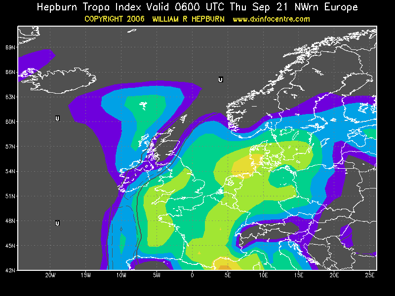 The same web-site also gives 5 day predictions as to the possible level of tropospheric propagation that can be expected too - very interesting.
Having recently installed a simple VHF antenna on my house, I thought I'd do the usual thing and tune around the various amateur repeaters to see what kind of coverage I was achieving. According to predictions that I had done, I expected to be able to just about receive transmitters from a maximum of 80 miles away (my location is nothing special). I was a bit surprised to discover that I could regularly hear stations from around 150 miles (225 km) away on 2 metres (145 MHz) and similar distance but less commonly on 70 cm (433 MHz). Indeed with the radio on in the background whilst working one day, a number of repeaters on the same channel at distances of around 150 miles faded in and out with alarming regularity.
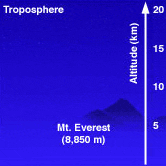 Of course the culprit in extending my range in this way is the troposphere (together with the fact that most amateur repeaters tend to be high up to give wide coverage to start with). It would seem that, even on an almost 'flat' day, there is enough going on in the atmosphere to enhance reception (and transmission) even for a fairly simple set-up in a fairly average location.
Now from an amateur radio perspective, this is great fun. From a 'professional' radio user's perspective this must prove a nightmare. Typically VHF frequencies will be re-used witin about a 80 mile radius, so that under totally flat conditions there is theoretically no potential for interference. However if 'tropogation' is as common as it would appear to be from my location, the levels of interference between commercial VHF (and to a lesser extent UHF) users must be a real nuisance - and there's nothing that can be done about it. Or is there...?
 Some television transmitters employ a technique known as 'beam-tilt' which points the signal from a transmitter slightly below horizontal. Doing this limits the range of the transmitter whilst at the same time reducing interference further away and producing a slightly stronger signal in the wanted coverage area. A beam-tilt of about 1 degree down from the horizon can make quite a difference. The problem is that it takes careful antenna design and often quite large and complex antennas to achieve beam-tilt so it isn't a solution for your average taxi company or security company.
A solution which is within the financial reach of most users is something known as CTCSS. This encodes a sub-audible (i.e. silent) tone onto each transmitter. Only transmitters and receivers set to use the same tone can hear each other. Such a system stops receivers from falsely hearing interfering transmitters - always assuming that the interfering transmitter has a different CTCSS tone to the one you want to receive. CTCSS, however, wouldn't stop the signal from causing interference, just stop you from hearing it.
Anyway, none of this is a problem for me. I'm just happy that my humble set-up is providing hours of endless fun (hmmm... must find something better to do) as I hear distant repeaters come and go!


