Friday 9 February, 2007, 16:06 - Amateur Radio
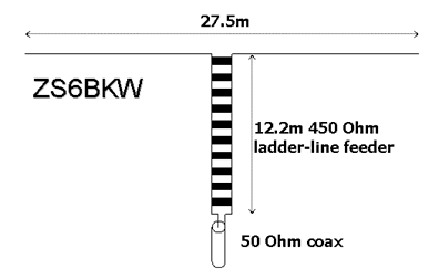
So having whet your appetite with details of the ZS6BKW multi-band antenna, I've finally finished my own installation of the antenna and will share my findings with you. The good thing about this particular multi-band antenna is that it covers the majority of the HF amateur bands that I'm interested in, particularly 80m, 40m, 17m and 12m, as well as 20m. 10m coverage (and 80m for that matter) is a bit poor.The original design shows two wires of 14.2 metres fed with 11.1m of 300 Ohm twin-feeder. However having scouted around the internet, I discovered that there is a revised version using 450 Ohm ladder-line feeder (which seems to be as easily if not more easily available than the 300 Ohm stuff). It has the main advantage that it's marginally smaller which, given the rather small size of my back garden meant that it should just squeeze into the available space.

One element of the original design that seems odd is the suggestion that no balun is needed at connection between the twin-feeder and the coax cable. Fundamentally, twin-feeder is a balanced system and coax is an unbalanced system and any radio (or audio) engineer will tell you that connecting one to the other is a recipe for disaster. In the case of radio systems, the upshot is usually that RF radiates from the outer of the coax increasing the potential for RFI and picking up more interference from neighbouring electrical devices (computers etc).
I managed to get a pole on the back of the house, the top of which is about 30ft (10m) above ground level and stretched the necessary 13.75m of copper wire (uncoated) from the pole to the two corners of the back garden which just fits. The whole installation is in the form of a sloping inverted-V with each end probably no more than about 12ft (4m) above ground level. The 450 Ohm ladder line is fastened along the soffit board, runs down the back of a plastic drain pipe and then along a wall until it meets the 50 Ohm coax - not straight or vertical or perpendicular to the antenna in any way. At this point, the coax (RG-58U which is sufficient as the run is so short) is wound 8 times through a iron powder ferrite to form a choke balun. A run of less than 10m of coax then terminates in the shack.
Like all experimenters, I cut both the wire (13.8m) and the ladder line (12.3m) slightly too long to allow for tweaking later. My first assembly resonated on 6.86, 13.76, 17.64 and 24.15 MHz (and less well on 3.4 and 28.44 MHz too) - on average about 4% low in frequency. The original ZS6BKW article does mention that installed in an inverted-V configuration, resonances would be a little low.
After reducing the length of the ladder line to the design figure of 12.2m and tweaking the length of the wires, ending up at 13.5m, the antenna now resonates beautifully on 7.1, 14.11, 18.06 and 24.8 MHz. On each of these frequencies, the SWR is below 1.3:1 indicating a pretty good match. There are also dips in SWR at 3.55 MHz (SWR 5:1) and 29.02 MHz (2:1) and, usefully, at 50.84 MHz (3:1) meaning I can also use the antenna on 6m too with a bit of a tweak of a tuning unit.
I haven't had the antenna in place long enough to determine its DX potential yet, but stations over 5000km away are readily audible. Having searched the net for articles on this antenna, I found very few so I thought documenting my experience might help others. Let me know how you get on.
3 comments
( 7541 views )
| permalink
| 


 ( 3 / 13886 )


 ( 3 / 13886 )

