Saturday 31 May, 2008, 08:23 - Amateur Radio
Posted by Administrator
One problem that radio amateurs (and professionals for that matter) regularly stumble across, is the problem of adequately surpressing the harmonics that are produced in their transmitter. Harmonics are frequencies which are on multiples of the actual signal being produced (e.g. a transmitter at 100 MHz will produce harmonics on 200, 300, 400, 500 MHz and so on...) and are a natural and largely unavoidable bi-product of the transmitter.Posted by Administrator
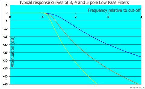
Normally a low pass filter is used to try and stop harmonics from reaching the aerial. Such a filter will be designed to allow the wanted frequency through with little or no attenuation, whilst attenuating harmonics by 30 dB or more (the level of filtering required depends on how bad the harmonics being produced by the transmitter are). However, there are some instances where the surpression offered by a low pass filter might not quite be enough to reduce the harmonics to a level where they are no longer a problem. The diagram below illustrates the typical response of various low pass filters.

Imagine an amateur radio station transmitting on 50 MHz. The second harmonic of this transmission is on 100 MHz, right in the middle of the FM broadcast band. If this happens to be the frequency of a local FM station, then even tiny amounts of harmonic radiation may upset neighbours trying to tune in.
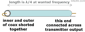
Years ago I stumbled across a device which is one of the simplest (and cheapest) harmonic filters around. It comprises of... a piece of coax. Yes, it's that simple. Or almost that simple. It's called a stub and works like this:
A quarter wave transmission line (i.e. a quarter wavelength of coax, twin feeder or similar) has the weird property that the impedance at one end of it will be the reciprocal of the impedance at the opposite end of it, at the frequency where it is a quarter wavelength long (this has to take account of the velocity factor of the line - more of this later). So, if one end of the quarter wave is a short circuit, the other end will be an open circuit.
A half wave transmission line exhibits the property that the impedance at one end, will be exactly the same at the other end (which is why some folk recommend making all patch leads a half wavelength long).
So how can these facts be used to make a harmonic filter. Simple! Using the previous example, if we cut a piece of coax to be a quarter wavelength long at 50 MHz and then short circuit one end of it, the other end will show an open circuit at 50 MHz so we can place it across the output of the transmitter with no effect (if you aren't sure how to connect it across your transmitter output you shouldn't be playing with transmitters in the first place). At 100 MHz, however, it will be a half-wave long and the short circuit at one end will appear at the other end. It will therefore allow the 50 MHz signal to pass and block the 100 MHz signal - the perfect harmonic filter.
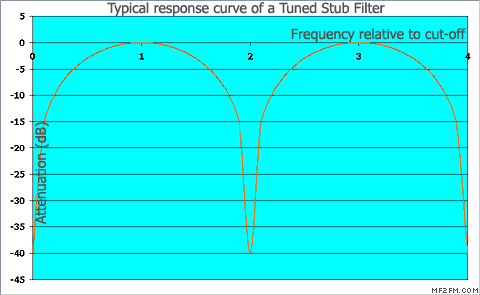
However, this pattern repeats such that the same 'stub' will also pass signals at 150, 250, 350 MHz and so on, and will block signals at 200, 300, 400 MHz and so on. Whilst this means that some harmonics are still passed unchanged, it does block half of them and in our particular example means that the problem signal that interferes with our neighbours' reception of the local FM station is addressed. Alternatively, it would simplify the design of the necessary low pass filter, potentially reducing the component count and hence cost. The frequency response of the stub (as connected across the output of a transmitter) is shown in the diagram below.

Making a stub couldn't be easier. Let's assume we are using standard RG-58 (URM-76) coax cable. This typically has a velocity factor of about 0.66 (meaning, freakily, that radio signals travel at only 0.66 times the speed of light inside the cable, compared to the speed in free space). Velocity factors vary between about 0.66 and 1 (foam filled coax has a factor of about 0.8).
 A quarter wavelength at 50 MHz is 1.5 metres long (300 divided by 50 MHz divided by 4). Multiplying this by the velocity factor gives a resulting stub length of exactly 1 metre. So, if we get 1 metre of coax, and short circuit one end of it, whilst connecting the other end across the output of our transmitter, it should have no effect whatsoever on the 50 MHz signal, but will short out the 100 MHz signal to the best of its ability.
Typically stubs of this nature attenuate the second harmonic by 30 dB. Careful tweaking to ensure that the second harmonic 'notch' is right on the second harmonic frequency can increase this to maybe 50 dB. Multiple stubs, separated by further quarter wave lengths of coax can be used to make the notch deeper.
The downside of such a filter is that it is frequency specific, so if we re-tune our transmitter to 52 MHz, with the harmonic falling now at 104 MHz, the second harmonic attenuation will be less (again multiple stubs, each on a slightly different frequency to the next can help here). Also, stubs of this type would be very large for low frequency operation (the same stub would require 14 metres of coax if the wanted frequency were in the 80 metre, 3.5 MHz band).
Nonetheless, the tuned stub harmonic filter has to be one of the simplest and cheapest ways to reduce harmonic emissions that anyone could make.
add comment
( 2152 views )
| permalink
| 


 ( 3.1 / 29518 )


 ( 3.1 / 29518 )

