Monday 27 April, 2009, 16:50 - Spectrum Management
Posted by Administrator
Today, Wireless Waffle's continuing series attempting to explain and simplify the many complex radio technologies, techniques and applications tackles perhaps one of the most complicated spectrum sharing schemes that exists. OFDM or 'Orthogonal Frequency Division Multiplex' to give it its full name is a clever method for sending data across the ether in such a way as to circumvent some specific, commonly occuring, problems. Though many people refer to OFDM as a modulation scheme, it is not! It is more accurately described as a multiplexing or sharing scheme and it can be used as an access scheme to allow the sharing of the spectrum between different users (in which case it becomes known as OFDMA - the 'A' being for 'access').Posted by Administrator
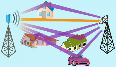
Before looking at what OFDM is, let's first consider the problems it aims to address. Chief amongst these are the problem of reflections and one of the upshots of reflections, frequency selective fading. The path between any two points on the radio landscape will rarely be straightforward. The signal may be received directly (i.e. the orange path in the picture below) as well as via reflections from various nearby and distant objects (the purple paths). Reflections from distant objects can commonly be seen on (analogue) television pictures where the main signal is followed by several 'ghosts', each representing the same signal arriving slightly delayed due to the path of the reflected signal being longer than that of the direct one. Where reflections are from nearby objects, the effect is somewhat different and manifests as 'holes' being punched into the received radio spectrum causing some frequencies to be severely attenuated whilst others remain largely unaffected.

Into this environment, we now introduce the requirement to transfer large amounts of data. For the sake of argument, let's choose 1 Mbps. If we modulate this data signal onto a radio carrier using basic BPSK (binary phase shift keying - the most basic of digital modulation schemes) the resulting signal has a bandwidth of around 1 MHz and a symbol period (ie the time representing each bit of data) of 1 microSecond. In order to successfully receive this signal, one key factor must hold true: reflections from any delays need to be significantly shorter than 1 microSecond. This is because:
* If a reflected signal arrives at the receiver 1 microSecond later than an undelayed signal, the receiver has finished receiving the bit concerned and has moved onto the next one. Thus the reflection is pure 'interference'. This is equally the case for delays of half a microSecond wherein the delayed signal has equal potential to interfere with the bit we are trying to receive and the one following it.
* A delay of 1 microSecond produces frequency selective fading notches every 1 MHz. As such, if the delay is longer than 1 microSecond, there is every chance that the notch in the frequency spectrum produced by the delay will punch a hole right in the middle of our wanted signal making it unreceivable.
A delay of 1 microSecond represents a reflected path that is 300 metres longer than the unreflected path (the speed of light times 1 microSecond). For a short distance link, this may not be difficult to achieve, but as the length of the link starts to exceed 300 metres, the potential for reflections causing problems increases. With a radio paths over 3 km long, for example, a reflective object which is more than 15 degrees away from the centre line of the path between the two ends will cause such a reflection - clearly a strong likelihood.
One solution to this problem is to minimise the potential for such reflections being caused by focussing the signal carefully between the two ends of the path using highly directional antennas. In this situation, reflections which are 'off-beam' will be heavily attenuated both at the transmit and receive ends of the link. In broadcast situations, however, whilst receiver antennas might be able to be directions, the transmit antenna is, virtually by definition, aiming to send out a signal over as wide an area as possible and in these circumstances reflections are inevitable.
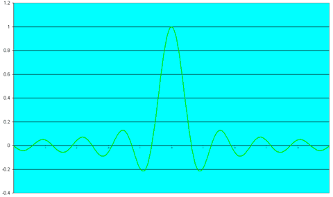
Another solution is OFDM! In OFDM, we take the 1 Mbps of data and break it up into a number of smaller, slower, data streams. For our example, let's break the stream into 100 smaller streams, each which carries only 10 kbps of data. If we modulate one of these streams onto a radio carrier using the same BPSK technique, it now occupies a bandwidth of just 10 kHz and has a symbol period of 100 microSeconds. As such, it can now tolerate delays which are 100 times larger than that the original 1 Mbps conterpart. The problem is that there is only one of them and we need to transmit 100. Normally, when transmitting a 10 kHz wide signal, we would need to leave some space either side of the signal to separate it from its neighbours. A factor of 50% is not unusual meaning that for each 10 kHz signal we might require 15 kHz of spectrum. For our 100 signals, we would therefore require 1.5 MHz of spectrum, making this significantly less efficient in spectrum terms than the single carrier solution. The diagram below shows the spectrum of a single data carrier.

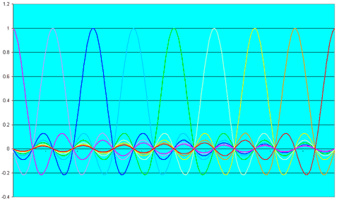
If, however, we modulate each of the adjacent signals intelligently and 'orthogonally' the requirement for space is negated and we can transmit the 100 carriers just 10 kHz apart, putting them back in the 1 MHz of spectrum that the original single carrier solution occupied. Orthogonal implies 'at right angles' and in essence, each adjacent carrier is modulated so that it is 'at spectral right angles' to its neighbour. The diagram below shows the spectrum of multiple orthogonal OFDM carriers. Note that at the centre of each carrier, the signals from all of the adjacent carriers are at a null of zero size.

 The upshot of this clever technique is that we can now transmit the data in the same amount of spectrum but in a way in which reflections and delays of much larger extents can be tolerated without effect, using 100 smaller, slower carriers rather that 1 large, fast one. The best non-technical analogy might be the need to transfer 100 bricks across an area of rough land. If we put all 100 bricks in a single wheelbarrow and push it along, it will get bumped and knocked and bricks will fall out. If there is a big enough obstruction the wheelbarrow will get stuck and nothing will make it to the other side of the land. Alternatively, if we put 1 brick in 100 separate wheelbarrows and push these over the land, whilst some may lose their bricks or be blocked, there is a much higher chance that a goodly proportion will make it to the other side.
An additional advantage of OFDM is that if there is interference on some of the spectrum within our 1 MHz channel, the single carrier solution fails, whereas for the OFDM solution only those carriers where the interference is present fail. Thus it is possible to maintain a connection in the presence of certain types of interference with OFDM. Being even cleverer, if we know which of the frequencies are affected we could change the error correction or modulation of the carriers on those frequencies to compensate for the problem, or even just not use them. Whilst all this would reduce the amount of data we could transmit, at least the connection would remain intact.
Transmitting and receiving OFDM is not straightforward and this is one of the reasons why it has not been used for mobile phones. Transmitters have a high peak-to-average power ratio such that an OFDM transmitter with an average output power of 1 Watt, may produce a peak output of 50 Watts or more, which is not efficient nor would batteries in handsets last long. Decoding the complex OFDM waveform is processor intensive and until recently, the processor power required would also drain batteries pretty pronto. Nonetheless, OFDM offers a number of advantages and many of the proposed fourth generation (4G) mobile standards will adopt it.
OFDM is used in many technologies including the DVB set of digital terrestrial broadcasting standards; for DAB and DRM radio; in some WiFi and WiMAX systems; and in various military and defence links. In these systems the number of carriers differs as does the modulation scheme which each carrier uses (which varies from BPSK to 64QAM) to adapt to the circumstances which are likely to be encountered.
OFDM is not an easy concept to grasp but we, at Wireless Waffle are always keen to try and debunk and demystify difficult radio ideas - we hope we have succeeded.
2 comments
( 2350 views )
| permalink
| 


 ( 3.1 / 33270 )


 ( 3.1 / 33270 )

