Friday 16 July, 2021, 13:17 - Amateur Radio, Broadcasting, Licensed, Pirate/Clandestine, Electronics, Radio Randomness
Posted by Administrator
Any radio transmitter needs a final output device whose job is to deliver the required amount of radio frequency (RF) energy. For the purposes of the Wireless Waffle lockdown project, an output power of 1 Watt was determined to be sufficient for most purposes. Most purposes including:Posted by Administrator
- having fun by designing transmitters during lockdown;
- generating enough RF to leak signals around the house whilst connected to a dummy load;
- warming up a 1 Watt resistor to 'just about untouchable' heat levels;
- driving a higher power amplifier to several hundred watts for whatever purpose that might be used for.
Most modern RF power devices are based on various versions of a field effect transistor (FET). One of the complexities of using these devices (such as the RD01MUS1) is that they require a specific bias voltage on their gate in order to perform correctly. That would be all fine and dandy except for the fact that the aforementioned 'specific bias voltage' is different for each transistor. That's right, not for each type of transistor, but for each and every transistor. This is due to the manufacturing process of FETs and although this might be to tight tolerances, it still leaves the end device with sufficient variability that individual adjustment is required. The only way to get this right in a circuit is to manually set the bias voltage. This is usually done by monitoring the amount of current that the device is drawing without any RF passing through it and then adjusting the bias voltage until the current consumption is correct.
Although setting the correct bias voltage is a 'do once and walk away' kind of activity which doesn't need to be re-done once set, the need for any kind of variable component on a design is a nuisance for several reasons:
- Variable components (such as resistors or capacitors) are prone to age badly. Variable resistors, for example, often go open circuit due to the ingress of dust, or through corrosion.
- If the circuit is not working properly, there is a tendency to start fiddling around with anything that is variable, which could end up with a completely incorrect setting of the variable component.
- There is also a tendency to fiddle with anything variable to see if 'more power' can be generated. Whilst some settings may result in a higher output power they are also likely to reduce the life of the output device, or worse, blow it up due to excess current consumption.
The simplest alternative to the FET bias problem is to not use a FET. Bipolar junction transistors (BJT) are biassed very differently and do not succomb to the same problems. Instead they can be set up with no bias at all and what's more, this arrangement is perfect for amplifying constant signals (such as generated by an FM transmitter) and even has it's own name 'Class C'. The thing is that BJTs are decreasingly common for RF given many other (as yet undiscussed) factors which favour the use of FETs.
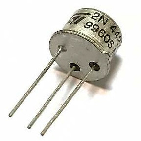
In the 1980s and 1990s, the 'go to' BJT for 1 Watt VHF transmitters was the 2N4427. This transistor would happily provide 1 Watt of output on most frequencies up to around 175 MHz and was relatively readily available and cheap. Manufacture of the 2N4427 ceased some years ago (some Chinese companies make a 'clone' which can provide 1 Watt at a push but is not the same device at all and is certainly not a drop-in replacement), and their availability and price are both becoming stretched. Whilst there are a number of equally aged transistors which can do a similar (or indeed a better) job, these too are no longer manufactured. A selection of these are listed below.
| Device | Output Power | Maximum Operating Frequency | Package | Gain |
|---|---|---|---|---|
| 2N6255 | 3 Watts | 175 MHz | TO-39 | 7.8 dB |
| 2SC730 | 1.5 Watts | 150 MHz | TO-39 | 10 dB |
| 2SC1947 | 4 Watts | 175 MHz | TO-39 | 10.5 dB |
| 2SC2329 | 2.5 Watts | 175 MHz | TO-39 | 13 dB |
| 2SC2131 | 1.6 Watts | 500 MHz | TO-39 | >7 dB |
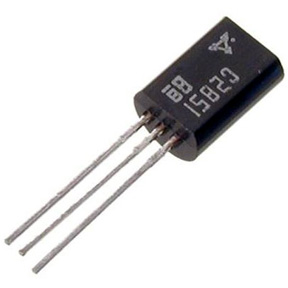
| 2SC2851 | 0.9 Watts | 175 MHz | TO-92 | 13.5 dB |
| 2SC3017 | 2 Watts | 175 MHz | TO-39 | 11 dB |
| 2SC4767 | 0.9 Watts | 175 MHz | TO-92 | 13.5 dB |
| MRF227 | 3 Watts | 225 MHz | TO-39 | 13.5 dB |
| MRF237 | 4 Watts | 175 MHz | TO-39 | 12 dB |
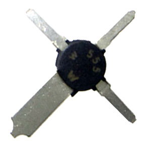
| MRF555 | 1.5 Watts | 470 MHz | Power Macro | 11 dB |
| MRF607 | 1.8 Watts | 175 MHz | TO-39 | 11.5 dB |
| NTE472 | 1.8 Watts | 175 MHz | TO-39 | 11.5 dB |
| SD1127 | 4 Watts | 175 MHz | TO-39 | 12 dB |
| TP2314 | 3 Watts | 175 MHz | TO-39 | 15 dB |
Just about the only device being manufactured today which could theoretically replace the 2N4427 is the MRF4427 which, given it's name, is supposedly a surface-mount replacement for the original device, but which, like the Chinese clones, is not a drop-in replacement. It has a very different gain profile and works up to much higher frequencies. The secondary issue with the MRF4427 is that being a surface mount device, it is much more difficult to get rid of the heat which is generated in a transmitter. RF output devices are often no more than around 60-70% efficient, meaning that a 1 Watt output transistor will also be generating around half a Watt of heat. Whilst this is easily gotten rid of on a traditional transistor by sliding a heatsink onto it, it is much more difficult to get rid of with a surface mount device (SMD). There are heatsinks available for surface mount devices but these are typically 'glued' onto the device which, though it may work, is not a perfect way. Better, perhaps, might be to try and get rid of the heat by distributing it around the printed circuit board (PCB).
 2N4427 (TO-39) |  2SC2851 (TO-92) |  MRF555 (Power Macro) |
For standard, double sided, FR4 PCB material, the thermal characteristics of the PCB are such that it will rise around 500°C per Watt per square centimetre of board. Copper via's between the top and bottom of the board can help reduce this. Dissipating a half Watt of heat in a centimetre square of PCB will therefore raise the temperature of the PCB by up to 250°C which is far too hot a temperature for any transistor to operate. However, if the transistor is mounted on a bigger piece of PCB, the heat will be distributed over a wider area and it becomes possible to get rid of half a Watt of heat without being left with a device whose main purpose would be boiling tin.
 Given all the above, for the Wireless Waffle lockdown project, after scouring the planet for sources of 30 year old transistors, the decision was eventually made to use an MRF555 device. This has nice, healthy sized leads which can be soldered onto pads on a PCB and the heat will be distributed across the PCB from all four pins of the device. It's still readily available (though no longer manufactured), relatively cheap, and being a device designed for UHF use, it loafs along at VHF frequencies, making it more efficient and therefore producing less heat. When mounted on a PCB, producing a Watt of RF, it heats up to around 65°C which is hot to the touch, but won't damage the device (or your skin too badly if you touch it).
 add comment
( 201 views )
| permalink
| 


 ( 2.7 / 1146 )


 ( 2.7 / 1146 )

