
How not to design transmitters and receivers (part 3: RF matching)
Sunday 25 July, 2021, 20:31 - Amateur Radio, Broadcasting, Licensed, Pirate/Clandestine, Electronics, Radio Randomness
Posted by Administrator
Part 1 of this series investigated an oscillator to generate an RF signal, and Part 2 looked at output devices which can produce 1 Watt. In order to connect one to the other, an intermediate amplifier is usually required. This provides additional gain to make sure that the output device has enough drive and buffers the oscillator from any changes in the output load. There are plenty of transistors (including surface mount) that are capable of providing the necessary amplification, so this is easy. For the Wireless Waffle lockdown project, an MPSH10 transistor was used. This is capable of a around 150mW of output, has plenty of gain at VHF frequencies, is cheap, and is readily available. A surface mount equivalent (the MMBTH10) is also available if needed. Posted by Administrator
Easy right? Drive the input of the transistor from the oscillator, and connect it's output to the RF power device. Not quite so. The main difficulty is that the input impedance of the RF output transistor is very low, whereas the output impedance of the preceding amplifier is relatively high.
The output impedance of the intermediate amplifier can be calculated based on the output power it is required to deliver. The equation is as follows:
Rout = V2/2Po
where:
- Rout is the optimum load resistance of the amplifier.
- V is the Voltage swing at the output of the amplifier. This is generally the power supply voltage minus the voltage drop across the transistor when it is in operation.
- Po is the required output power in Watts.
How, then, to match a 300 Ohm output impedance to a 3 Ohm input impedance? Inter-stage impedance matching can be achieved either via transformers (which can offer broad bandwidth solutions), or by various arrangements of capacitors and inductors (which tend to need to be tuned around specific frequencies). The ratio of turns in a transformer is the square root of the ratio of the impedances, so in this case, a transformer would have to have a turns ratio of roughly 10:1. Such large impedance transformation ratios are difficult to achieve with transformers (for various as yet undiscussed reasons) and so an alternative approach is needed.
Impedance matching using basic networks made of inductors (L's) and capacitors (C's) can easily be done, however a simple two or three component network capable of converting from 500 to 3 Ohms would require a circuit with a minimum 'Q' factor of around 11. The Q factor determines the bandwidth of the network and roughly speaking if you divide the operating frequency by the Q, you get the half-power (3dB) bandwidth of the network. At 100 MHz for example, such a network would have a bandwidth of around 9 MHz, or put another way plus or minus 4.5 MHz from the centre frequency. This would work, but would clearly require re-tuning if the transmitter wanted to operate at different frequencies within the FM band, and as has been previously stated, any part that needs to be adjusted is subject to many potential failure modes.
So how's about a more complicated LC matching network? Calculating the necessary component values for LC matching networks with up to 4 components can be done relatively easily, and to make matters even more straightforward there is an online tool which will do it for you. The Impedance Matching Network Designer will do all the difficult sums. Just enter the input and output impedance you are trying to match and the web-site will do the necessary maths.
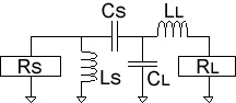 Entering 3 ohms and 300 ohms into the values for the load and source resistance respectively, results in a range of possible network topograhpies (fancy words which mean the relative positions of the L's and the C's). Some of these are more useful than others, and the one selected was the L-C-C-L network as depicted on the right. The values given by the calculator are as follows:
LS = 159 nH
CS = 17.6 pF
CL = 159 pF
LL = 14.3 nH
The advantage of this arrangement is that LS can be made the inductor which sits between the collector of the transistor and the power supply, providing it's power source and thus slightly reducing overall component count. Simulating this network using the excellent Micro-Cap tool (which is amazingly now free) from the appropriately named Spectrum Software and driving it directly from the collector of the MPSH10 showed a rather lumpy frequency reponse (shown below in blue - click for a larger version).;)
After some tweaking it was found that changing CS to 15 pF and CL to 180 pF, and adjusting LS and LL accordingly gave a better and less lumpy match between the two stages, and at the same time had sufficient bandwidth that no re-tuning of the network is needed across the frequency range 88 to 108 MHz (the red curve on the graph). This, incidentally, does not mean that changing the values can not give a better result. A 'broadband' matching network will almost always represent a compromise on the overall matching efficiency and playing around with the values can give additional gain on a particular frequency at the expense of a reduction in gain on a different frequency. However, as long as the output device and its driver have sufficient oomph to produce the required output across the whole frequency range, there is little to benefit from the extra gain. Of course, in real life, with actual (and not simulated) components the values may need further tweaking.
add comment
( 332 views )
| permalink
| 

 ( 3 / 1182 )
( 3 / 1182 )