
How not to design transmitters and receivers (part 6: prescalers)
Wednesday 25 August, 2021, 09:39 - Amateur Radio, Broadcasting, Licensed, Pirate/Clandestine, Electronics, Radio Randomness
Posted by Administrator
Part 5 of the series 'How not to design transmitters and receivers' discussed phase locked loops (PLL) and the fact that programmable dividers (divide by 'N') are required in order to make a PLL which can operate on different frequencies. Such a divider would need to be able to take radio frequency (RF) signals at its input before doing the dividing. Off-the-shelf CMOS logic chips in the 74HC series are generally capable of operating at frequencies up to 50 or 60 MHz (and in some cases up to 70 MHz). These could therefore be directly used as dividers in low frequency circuits where a solid 5 Volt signal can be fed into them, but anything operating at over about 70 MHz, or which produces a smaller output, requires some other technology.Posted by Administrator
This is then the realm of the 'prescaler'. A prescaler is basically a high frequency divider, often with a fixed division ratio, or in some cases with a limited number of fixed ratios. In most cases they are also designed to accept a low-level RF input rather than needing 5 Volts peak-to-peak.
There are an enormous number of prescaler IC's available, some dating back to the early 1980s. Thankfully, a useful look-up table of prescaler specifications is available online. The requirements for the Wireless Waffle lockdown project are that the prescaler must meet the following specifications:
- Be able to operate at frequencies down to around 25 MHz (so that the half-frequency oscillator can be used in Band-I, i.e. around 50 MHz, if needed).
- Be able to operate at frequencies up to around 600 MHz (so that future UHF designs can use the same chip).
- Have a division ratio of at least 40 (so that a 600 MHz input will be brought well within the frequency range of other digital components).
- Accept a reasonable and if possible wide range of input powers (to simplify the design of any circuitry feeding it).
- Be reasonably cheap (of course!)
- Be relatively widely available (so that there won't be any problems in getting hold of any for future projects).
To find a suitable device, it was necessary to carefully peruse the exact specification sheets of various devices. Most have a 'guaranteed operating range' which is the combination of input frequency and input power over which they will perform perfectly. However, the specification sheets often contain performance curves which show input power and input frequency combinations that should work fine but are not guaranteed. A number of prescalers have guaranteed operating ranges which go as low as 50 or 70 MHz, but the datasheet shows that they will operate below this range, generally if they are driven with slightly higher input power.
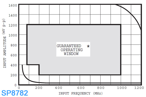
Take, for example, the above chart taken from the datasheet for an SP8782 prescaler. The guaranteed operating window covers the frequency range from 200 MHz to 100 MHz with an input level of 200 mV peak-to-peak, descending to around 50 MHz (according to the datasheet, though the chart makes this look more like 70 MHz) if the input level is increased to 400 mV. However, even lower and higher frequency performance is possible. In the case of lower frequencies, it would appear to operate down to as low as maybe 25 MHz and as high as 1200 MHz if the input levels are suitably adjusted.
Slight aside: The MB501 requires a 2K (or thereabouts) pull-down resistor on its output to function. This isn't optional, it's mandatory. It's easy to forget this and wonder why the circuit isn't working...!
After much research, the MB501L was selected for the Wireless Waffle project. This has a guaranteed minimum operating frequency of 10 MHz, a maximum of 1100 MHz, and over this range will perform correctly with an RF input ranging from -4 to +6 dBm (1 milliWatt give or take). It has a pre-settable division ratio of 64, 65, 128 and 129. What's more one can be bought online for around £1.50 and seems relatively widely available despite originally being of mid 1980s vintage.One other thing to consider when using prescalers is that they often do a rather bad job of isolating their inputs from their outputs (and their power supply rails). This means that the divided signal can easily get into whatever they are connected to, and in particular the RF inputs, causing spurs on the RF signal at multiples of the divider output. Take an example of a 64 MHz oscillator, connected to a device such as the MB501L set to divide by 64. The output frequency of the divider will be 1 MHz, and if care is not taken, this will find its way back into the oscillator meaning that unwanted spurs 1 MHz from the oscillator (i.e. at 63 and 65 MHz) will be produced.
Solutions to this include a buffer between the oscillator and the prescaler, or the introduction of sufficient loss (i.e. through a resistor) between the two to minimise the impact of any lack of isolation in the prescaler. Unless there is an excess of RF power to play with, the best option is to use a buffer. There are a myriad of RF buffer schematics online to choose from. In this application, one of the main criteria is the amount of isolation between input and output as this is the purpose to which the buffer is being put. Another design criteria is for the buffer to produce the right level of output to drive the prescaler at its preferred input levels. Field effect transistor (FET) buffers are particularly good when it comes to input/output isolation, and a very simple buffer can be constructed with the minimum of components. Bipolar transistors (BJT) can also be used, but tend not to have such good isolation. Two such buffer circuits are presented below.
;)
The Junction-FET (JFET) circuit has a very high input impedance (largely set by the value of the 220K resistor from its gate to ground) and good isolation. The input impedance of the BJT circuit will be much lower and isolation poorer, so what, you might ask, is the benefit of the BJT approach. The answer is simple: some companies who manufacture printed circuit boards (PCBs) can also assemble surface mount devices (SMD) on the board at very low prices, and the 2SC3356 shown in the schematic is a device which these manufacturers have in their low-cost stock room, whereas they rarely have JFETs available.
At this point we nearly have all the building blocks necessary to make a fully synthesised transmitter bar a couple - the 'divide by N' block, and the 'phase/frequency comparator'. More, then, to follow soon.
2 comments
( 426 views )
| permalink
| 

 ( 3 / 1456 )
( 3 / 1456 )