Friday 3 September, 2021, 08:46 - Amateur Radio, Broadcasting, Licensed, Pirate/Clandestine, Electronics
Posted by Administrator
The next functional block that is required to complete a transmitter (not a receiver for which there are many other blocks to consider) is the 'divide by N' device. In principle, all that is required to achieve this function is a counter which will count up (or down) until it reaches a particular number (or zero), indicate this (i.e. with some kind of output pulse) and reset itself. Posted by Administrator
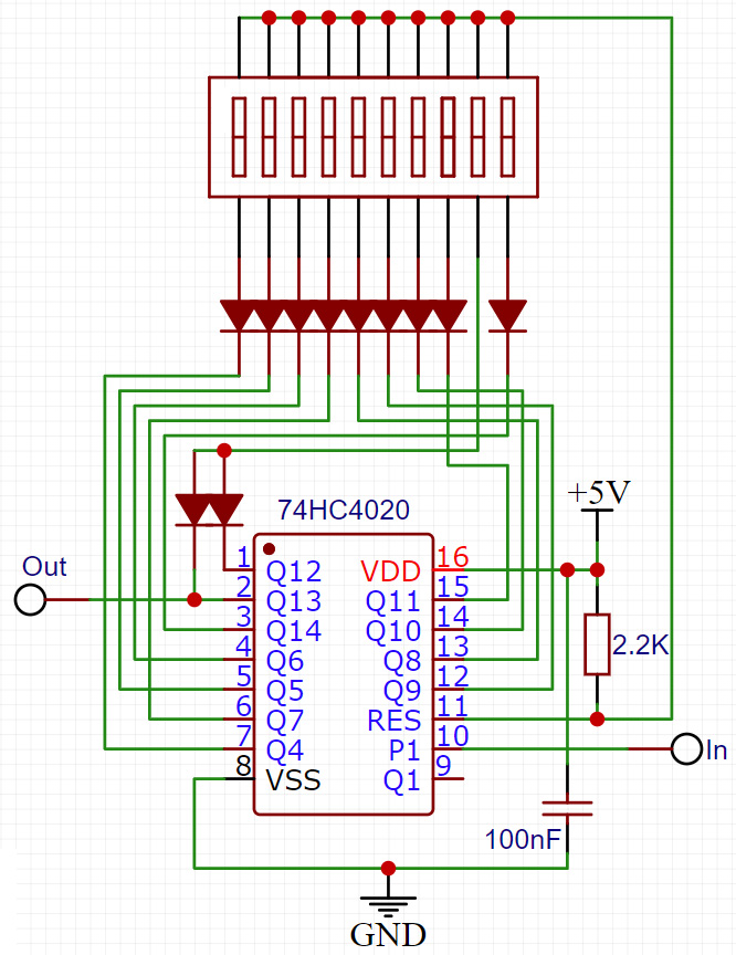
There are many ways of achieving this from the use of logic ICs to dedicated counter ICs. Let's begin with the logic IC approach. Any binary counter which has a way of being reset to zero can be used as a counter. It's simply a matter of detecting when the right combination of bits have reached '1' and then resetting the counter and starting again. A simple way of doing this is using a CMOS 4020, 4024, 4040 or 4060 counter. To check when a selected number of bits are all 1's, connect the cathode of a number of diodes to the relevant bits, connect the anodes together to a common point and then join that point to positive via a suitable resistor. When any of the bits are zeros, they will pull the common point down to ground through the diodes. Only when all of the bits are 1's will the common point go high. An example circuit, including a switch to decide which diodes (and thus which bits) are tied to the common point is shown to the right (click for a larger version).
 Pin 11 of the 74HC4020 counter is connected to the positive supply by the 2.2K resistor, and will reset the counter to zero when it goes high. However, this is the common point for the diodes which will pull this point down to ground when any of the bits of the counter switched into circuit are zero. Only when all the bits which are switched into circuit go high will pin 11 go high, at which point the counter resets and will start counting again at the next input clock pulse. The output of the circuit could be taken from the common point, however the reset pulse is very narrow and may be missed by, for example, a slower operating phase comparator. In this example, the output is taken from the second most significant bit, which will give something nearer to a square wave. Note that the diodes have been arranged so that the switches are in binary significance order with the most significant bit being on the right hand side and the least on the left.
This circuit works very well, however it has one minor flaw and one major, yet surmountable one. The minor flaw is that a finite amount of time is required between the common point going high and the counter being reset. This time is measured in nanoseconds, however if the counter is running particularly quickly (i.e. at frequencies measured in MHz where each bit is less than a microsecond long) this delay means that the counter counts to 'N and a bit', the 'bit' being the extra time taken for the counter to reset. Some circuits set the counter to 1 less than is required, and use an additional flip-flop to count the last bit whilst giving the counter time to reset, but this adds extra complexity (and thus cost) to what is an otherwise simple circuit.
The major yet surmountable flaw is that each output pin of the divider has a square wave on it. These pins generate small but nevertheless detectable harmonics right across the radio spectrum. If a prescaler is noisy, these things are deafening and as receivers are very sensitive, these outputs will produce interfering signals at almost any and every frequency to which you may wish to tune unless extreme care is taken to shield this part of the circuit from the receiver parts. Thus, whilst such a design is great in a transmitter (assuming a buffer and/or prescaler is used between the VCO and it), it is a veritable pain in the back-side in a receiver.
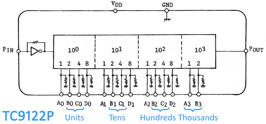
There are, thankfully, a number of pre-settable counters which overcome both of these problems. An old device but one which is very easy to use and understand is the TC9122P.

The TC9122P can count from 1 to 3999 and its inputs are in binary blocks of 10 (otherwise known as binary coded decimal, BCD). So to divide by 896 or 1079, the required setting would look something like:
| 0 | 8 | 9 | 6 | 1 | 0 | 7 | 9 | |
| 00 | 1000 | 1001 | 0110 | 01 | 0000 | 0111 | 1001 |
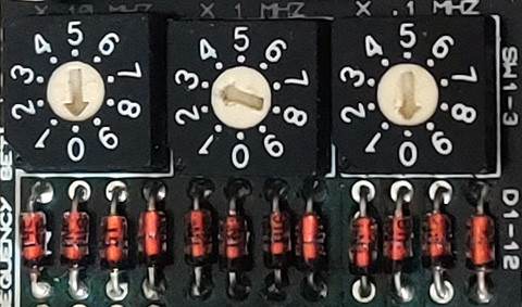
 Rotary BCD switches are available which could be directly connected to the inputs and then frequencies could simply be 'dialled' in. The same result can also be achieved with a 4059 which is a little more complicated as it has a number of different counting modes including, though, BCD. An example of using BCD switches to dial up a frequency is illustrated on the left (which is taken from a Broadcast Warehouse 1 Watt FM exciter).
In part 7 of the 'How not to design transmitters and receivers' the MC145151 was introduced. This IC includes a divide by N counter which is a straightforward binary (and not BCD) counter. One oddity with that particular chip is that the input pins to the counter are tied high with an internal resistor meaning that pins which need to be set to zero should be connected to ground, whereas with many other counters it is usually the pins which need to be set to one which should be connected to positive.
An example of using standard binary to set the numbers 896 and 1079 are shown in the table below.
| Decimal | Binary |
|---|---|
| 896 | 01110000000 |
| 1079 | 10000110111 |
One thing that was noticed when considering using straight binary (and not BCD) for programming frequencies across the FM band is that to select numbers over 1023 (e.g. if using a reference frequency of 100 kHz and wishing to access the whole FM band such that numbers up to 1079 are required), 11 binary digits are required (that's eleven, not three). Nice, cheap, binary switches are available in 10 or 12 bit versions. Whilst it would have been easy enough to use a 12 bit switch and leave one bit unused, it would be even nicer to find a way to use a 10 bit switch.
 Such a way was found. If we call the most significant bit 'bit 11' then bits 9 and 10 can be tied together (as has actually been done in the counter circuit above). This means that any binary number from '01100000000' representing 768, to '10011111111' representing 1279 can be set. Assuming a 100 kHz reference frequency, anything from 76.8 to 127.9 MHz can be set using just a 10 bit switch. In addition (though potentially rather uselessly in this application) any other binary number in which bits 9 and 10 are the same can also be selected. Thus numbers from '00000000000' (0) to '00011111111' (255) and '11100000000' (1792) to '11111111111' (2047) could also be set, potentially representing frequencies from 0 to 25.5 and 179.2 to 204.7 MHz.
We now have nearly all the blocks necessary to create a variable frequency phase lock loop based FM transmitter. There's still the reference oscillator (which is relatively trivial) and low pass filtering to go.
add comment
( 241 views )
| permalink
| 


 ( 2.6 / 1044 )


 ( 2.6 / 1044 )

