Thursday 4 November, 2021, 11:33 - Amateur Radio, Broadcasting, Licensed, Pirate/Clandestine, Electronics
Posted by Administrator
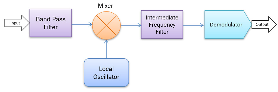
Now that the design of the transmitter has been completed, it's time to turn attention to a receiver. The diagram below shows the blocks which make up a receiver.Posted by Administrator

This works as follows:
- The incoming signal is first sent through a band-pass filter. The job of this filter is to ensure that only signals on the frequency (or frequencies) of interest are sent to the receiver. This makes the job of the receiver more straightforward and, in particular, needs to ensure that signals on the receiver's 'image' frequency (more of which later) are stopped from entering the next stages.
- Jumping to the end of the receiver, a second filter, the intermediate frequency (IF) filter has the job of filtering out any signals on frequencies adjacent to the one that is to be received. This filter has a much narrower frequency response than the band-pass filter at the receiver's input. For a wide-band FM signal, this would typcally have a bandwidth of 250 kHz, whereas the band-pass filter may cover 10 MHz or more.
- The de-modulator has the job of turning the received signal into some form of output. In the case of an FM receiver, this is audio, but this could equally be a digital output if the transmission was in some digital format.
- Sitting between the band-pass filter and the IF filter is a mixer, which is fed both the incoming received signal and some other frequency, usually generated by either a crystal (for a fixed frequency receiver) or by a PLL. This oscillator generating this signal is known as the local oscillator (LO). The mixer operates on the 'heterodyne' principal (invented in 1901 by Reginald Fessenden which is a story worthy of a future post). This mixer is non-linear and as such will 'mush up' the signals and produce all manner of other signals. If the incoming signals are two frequencies f1 and f2, then amongst other things, the mixer will produce 2xf1, 2xf2, f1-f2 (or vice versa), f1+f2 and many other variants. Of most interest to us are f1+f2 and f1-f2. If we take either of these outputs to be the frequency at the centre of the IF filter (usually 10.7 MHz), and f1 is the incoming signal, then if we set f2 at 10.7 MHz above or below the incoming signal frequency, one of the outputs from the mixer will be the IF frequency.
- Assume that the wanted receive frequency is 100 MHz and that the IF frequency is 10.7 MHz, then the LO needs to be at either 89.3 MHz (100-10.7) or 110.7 MHz (100+10.7).
- However, if the LO is at 89.3 MHz, the receiver will perform equally well, not just at 100 MHz but at 10.7 MHz below 89.3, i.e. 78.6 MHz (89.3-10.7). It is the job of the band-pass filter, therefore, to ensure that any signals at 78.6 MHz are rejected and that only the 100 MHz signal passes to the mixer.
- A similar situation occurs if the LO is at 110.7 MHz, as the receiver will then also receive signals at 121.4 MHz (110.7+10.7).
Choosing the correct LO frequency is not trivial and it is important to consider the image frequency. Take a receiver tuned to 71.6 MHz. This would have two possible image frequencies, depending on whether the LO is 10.7 MHz below or above 71.6 MHz. If the LO is below (i.e. 60.9 MHz) then the image frequency would be 50.2 MHz. If the LO is above (i.e. 82.3 MHz) then the image frequency would be 93 MHz. In the first instance the image frequency is right on top of the most active part of the amateur radio 6 metre band, and in the second it is on an FM band frequency. Either of these may lead to interference, and a well designed band-pass filter would be needed to ensure that only the wanted frequency was passed through.
One other important consideration is that receivers are, by their nature, very sensitive devices. Incoming signals as low as 1 microVolt are sufficient to produce an output. This means that very careful attention needs to be paid to the design, to ensure that the minimum of additional noise or unwanted signals are produced. This is especially the case if a PLL is used as the LO. The PLL needs to be clean. As discussed previously, pre-scalers used in PLL's can be very noisy, and care needs to be paid to ensure that none of the output from the pre-scaler is in any way capable of getting into the receiver. In addition, and digital signals (such as the output from the pre-scaler) need to be routed on tracks as short as possible, as, being square waves, they are full of harmonics which could easily fall on a frequency which would interfere with the receiver.
Lots to think about then, and in ensuing installments of this series, the additional building blocks needed for a receiver will be considered.
add comment
( 362 views )
| permalink
| 


 ( 2.8 / 1495 )


 ( 2.8 / 1495 )

