Wednesday 27 February, 2013, 08:20 - Amateur Radio, Spectrum Management, Satellites
Posted by Administrator
Over in Brussels, the European Commission, through the direction given to it by the Radio Spectrum Policy Programme (RSPP), is trying to identify 1200 MHz of spectrum that can be made available for 'wireless broadband' services. At present there is 1025 MHz of spectrum available for such services including:Posted by Administrator
| Band | Allocation | Total Spectrum |
|---|---|---|
| Digital Dividend | 791 821 // 832 862 MHz | 60 MHz |
| 900 MHz | 880 915 // 925 960 MHz | 70 MHz |
| 1800 MHz | 1710 1785 // 1805 1880 MHz | 150 MHz |
| 2.1 GHz (FDD) | 1920 1980 // 2110 2170 MHz | 120 MHz |
| 2.1 GHz (TDD) | 1900 1920 MHz 2010 2025 MHz |
35 MHz |
| 2.6 GHz (FDD) | 2500 2570 // 2620 2690 MHz | 140 MHz |
| 2.6 GHz (TDD) | 2570 2620 MHz | 50 MHz |
| 3.6 GHz | 3400 3800 MHz | 400 MHz |
| Total | 1025 MHz | |
Finding another 175 MHz to make the goal of 1200 MHz is therefore surely not such a big ask. However, there are issues with the spectrum that is currently available. The 3400 3800 MHz band accounts for 400 MHz or a good third of it and despite already being allocated to broadband wireless in Europe, it has not been very popular. The slow take-up is partly due to a lack of mass market products for the band and the poorer propagation at these higher frequencies, but is also due to the need to protect certain C-Band satellite downlinks which remain in the band. This also forms the 9cm amateur band. It therefore seems sensible that if new spectrum is to be found, it ought to be below 3 GHz in order that it will prove popular enough to actually be put into use.
 To try and identify 'underused' spectrum, the European Commission is conducting a spectrum inventory whose purpose is to firstly examine the availability and use of spectrum and then to consider the future needs to try and match supply with demand. The first part of this inventory, a study which examined the extent to which each spectrum band is used was published in late 2012. The initial findings of the consultants who undertook the study were that the bands with the lowest current usage and thus which might be candidates for re-allocation were:
- 1452 1492 MHz. This band is set aside for DAB radio services, however it has remained virtually unused. The ECC have now recommended the re-allocation of this band for mobile services after pressure from Ericsson and Qualcomm to do so. This is therefore a 'no brainer' or a 'done deal'.
- 1980 2010 // 2170 2200 MHz. This band is currently allocated for 3G mobile satellite services to complement terrestrial 3G services. One satellite (Eutelsat 10A) was launched with a payload that is active in this band, but it failed to deploy the dish correctly and as such the band remains largely (though not completely) unused. It would seem churlish to take this away though, when there is still scope for it to be commercialised for its intended purpose. Perhaps some form of sharing using a complimentary ground component could be envisaged.
- 3400 3800 MHz. This was identified as being underused 'Quelle surprise' as they say in Brussels!
- 3800 4200 MHz. This is also part of the C-Band satellite downlink frequency range but has also been used for fixed links in some countries. Fixed links can be carefully controlled so as to avoid interference to satellite ground stations: it is unclear how a more widespread roll-out of services in this band would be feasible. This also fails the 'below 3 GHz' test.
- 5030 5150 MHz. This band is allocated for aeronautical use and was intended to be used for a new microwave landing system (MLS) to replace existing landing systems and for aeronautical mobile satellite services (AMSS). Very few airports or airlines have adopted MLS (London Heathrow and British Airways being two of the few who have done so) and no AMSS services in the band have been launched. If 3.5 GHz is not popular though, it seems unlikely that 5 GHz will be any more welcome.
- 5725 5875 MHz. This is a band which is available on either a licence exempt or a lightly licensed basis in most European countries for use with WiFi (802.11a) and other low power services. Being well over 3 GHz it is unlikely to be popular. It also forms a large chunk of the 6cm amateur band.
One option on the table, though not identified through the inventory, is the frequency band 2300 2400 MHz. It was identified at the 2007 World Radio Conference as a candidate for IMT (the ITU code for wireless broadband). It is already in the 3GPP standards for LTE, where it is known as the mysterious 'Band 40'. The ECC has considered the use of this band for wireless broadband services and concluded that it is quite possible. Sweden and Australia have already handed all of the band over to wireless broadband use, and many other countries (especially in Asia) have licensed part of it. One of the big problems with this band in Europe is that it is heavily used by governmental (read 'defence') services who are already smarting from the loss of many other bands over the past years and are in no mood for another re-farming exercise to release this band. Oh, and it represents the vast portion (and the most useful bit) of the 13cm amateur band.
 Meanwhile, over in the USA, the FCC has also recently assessed the possibility of reallocating some the frequency band 1675 -1710 MHz for wireless broadband uses. This band is currently used for the downlink for meteorological satellite services, however few satellites venture above 1695 MHz (with the possible exception of a couple of NOAA satellites, the Chinese Feng Yun satellites and the polar orbiting METOP) and there is almost nothing above 1700 MHz, unless you count satellites yet to be launched (such as GOES-R).
Given the location of this spectrum, directly adjacent to the existing 1800 MHz band, and given that the associated pairing is also largely unused it might easily be possible to, say, extend the 1800 MHz band by 2 x 10 to become 1700 1785 // 1795 1880 MHz. Keeping the spacing between the up and downlinks would simplify the adoption of the new spectrum (in the same way that GSM became E-GSM). The 10 MHz gap in the middle is rather small which can cause handset manufacturers problems, but there are ways this could be dealt with. The loser here (other than some yet-to-be-launched satellites who could surely locate their downlink in the remaining part of the band) are radiomicrophones who are allocated 1785 1800 MHz. A screaming case of 'use it or lose it' if they are to retain this allocation.
And whilst we're pairing up things, how's about extending the 2.1 GHz band? The lower part of the pair, 1900 1920 MHz, is already licensed, albeit for TDD services. The upper part of the pair, 2090 2110 MHz is another of those military bands that would prove difficult to squeeze. The bigger problem here is that it contains sensitive satellite uplinks that are easily interfered with. Nonetheless, there was a terrestrial wireless network licensed in the band in the UK (Zipcom), if never actually launched.
So far, we have identified the following extra spectrum:
| Band | Allocation | Total Spectrum |
|---|---|---|
| L-Band | 1452 1492 MHz | 40 MHz |
| Extended 1800 MHz | 1700 1710 // 1795 1805 MHz | 20 MHz |
| Extended 2.1 GHz | 1900 1920 // 2090 2110 MHz | 20 MHz (20 MHz was already available) |
| 2.1 GHz MSS sharing | 1980 2010 // 2170 2200 MHz | 60 MHz (shared with satellite) |
| 2.3 GHz | 2300 2400 MHz | 100 MHz |
| Total | 240 MHz | |
That makes 240 MHz of potential new sub-3 GHz spectrum without too much pain and done in a way that is largely compatible with existing mobile bands, though not with existing defence or satellite sensitivities. Given the recent auction prices for spectrum, 240 MHz across Europe is worth something in the region of 75 billion Euro. So what would it cost to release it?

- L-Band is free in every sense of the word. Except possibly in the UK where it is owned by Qualcomm but presumably as they have been lobbying for it to become available for mobile services, they would have no qualms about using it for such. Cost: peanuts.
- Extended 1800 MHz The main affected party here are some meteorological satellite downlink sites. These are few and far between and could be protected through the use of an exclusion zone. Cost: cashew nuts.
- Extended 2.1 GHz The number of military satellites using the band 2090 2110 MHz is difficult to ascertain (for obvious reasons). There is also a need to re-farm the band 1900 1920 MHz. Cost: macadamia nuts.
- 2.1 GHz MSS sharing In theory there is nothing to stop this taking place even with a satellite already launched. To be completely fair, it would only be reasonable to recompense the licensees (Solaris and Intelsat) for their investments. Cost: pistachio nuts.
- 2.3 GHz Those defence boys have big toys (and big guns) that would be costly to replace. That being said, only around 40 MHz of this band is necessary if the target is 175 MHz and not 240 MHz. Surely releasing 40 MHz cant be that difficult no matter how big your toys. The fact that the band is destined for TDD means that it doesnt even need to be the same 40 MHz in each country. Cost: pistachio nuts.
Alternatively, perhaps radio amateurs who stand to lose the 13cm, 9cm and 6cm bands might wish to launch a counter-bid? After all, theyre replete with nuts (in a good way) !
add comment
( 2002 views )
| permalink
| 


 ( 3.1 / 2385 )


 ( 3.1 / 2385 )
About 18 months ago, the Wireless Waffle team wrote a paper on the topic of what radio amateurs in the UK might have to pay if spectrum pricing was applied to the spectrum they use. The paper was offered to the RSGB and to Practical Wireless as material that could be used for an article in their prestigious magazines.
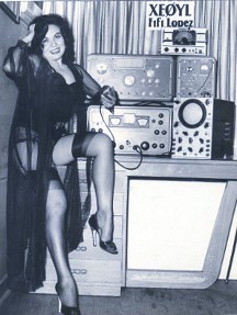 The RSGB indicated that it was not the sort of article they normally published as it didn't have antennas in it or any pictures of people standing on a mountain or remote desert island. Practical Wireless never responded as they were too busy assessing the merits of the latest amateur radio gizmo to come from Latin America (see right) and the whole thing got shoved to the bottom of the 'to do' pile and forgotten about. At least I think that was what the RSGB and PW said, the old memory is a bit hazy on the subject.
Whilst the material contained in the paper is now around a year old, it still makes for interesting reading and it is almost certain that Wireless Waffle readers will find it worth the time to study. Rather than think what to do with it next, it has been uploaded to the web-site and is now available for anyone to download and read.
So, for your reading pleasure, we present 'The Duffer's Guide to Spectrum Pricing. Pour yourself a beer, turn on your VHF radio, and have a read. Then, if you are a radio ham, realise how lucky you are to be able to afford that beer you just poured yourself!
Saturday 11 February, 2012, 12:52 - Amateur Radio, Electronics, Radio Randomness
Posted by Administrator
A while ago on Wireless Waffle, I commented on the daily loss of service that was occuring on my home broadband (ADSL) connection. It seems that this struck a chord with a number of people and remains one of the most commented-on articles on the site.Posted by Administrator
The question is, 'can anything be done to fix this problem'? The answer seems to be, that for a few pounds (a few and a bit Euros, or a few and a half Dollars) you can easily make a device which will provide additional filtering on your ADSL line and help with the problem of interference on the line. This solution is not a 100% guarantee of an improvement but does help and has resulted in an enormous (almost complete) reduction in drop-outs and, to boot, an increase in connection speed on the Wireless Waffle line!
The increase in broadband connection speed is perhaps an odd outcome but this is a result of a more stable connection on the line. This is why... The equipment at the exchange sets a target 'signal to noise (s/n) threshold' for each line depending on how reliable the line is. If the line continually drops out, the target s/n is increased to provide an additional 'safety margin' to try and stop future drop outs. If the line remains stable for a while (typically a couple of weeks), the exchange notices the difference and will lower the target s/n threshold. Each change in threshold is typically 3dB (a doubling or halving of power) and results in an approximately 500 kBps change in line speed. The Wireless Waffle line was originally synchronised with an s/n threshold of 12dB and a speed of just over 2 Mbps. As a result of applying the solution about to be described below, over a month or so, the target s/n was reduced (by the exchange) to just 6dB and the connection speed is just over 3.5 Mbps! Even with only 6dB s/n the line has remained completely stable for over two months and has not dropped out again once.
So how does this miracle solution work. Well, the first step is to gather the teeth of some bats at full moon when wolves are howling. Add to this, three drops of lizard spittle and some onyx droppings. Only kidding! It's not magic it's just simple electronics!
The solution comprises two simple pieces:
- A common mode choke which serves to remove any non-common mode signals from the line
- A low pass filter to get rid of any noise on the line which is outside the range of the ADSL signals
The low pass filter just stops any signals arriving on the line which are not needed for ADSL from getting into your modem and causing havoc. This could be strong short or medium wave broadcast signals which appear after dark, or could be strong local transmissions from a nearby radio amateur. Three different filter designs are presented which have differing degrees of effectiveness and you can choose which is the best for your situation.
To make the Wireless Waffle Anti-Daily Service Loss (or WWADSL) device, you will need:
1. Two pieces of (single core) wire, around 30 cm long
2. A ferrite toroid (eg FT50-43)
3. Two capacitors (either 1nF or 470pF - see below)
4. Two inductors (either 3.3uH, 4.7uH or 6.8uH - see below)
5. Six pieces (three pairs) of 'chock block'
6. An old phone socket to ADSL modem lead
No soldering is required and all the parts are reasonably readily available.
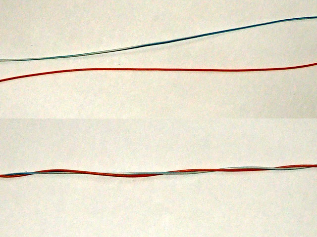 Let's start with the choke. This simply consists of two pieces of (single core) wire, twisted together and then threaded through a small ferrite toroid. The exact number of turns is not critical, but the type of toroid is important. You need a ferrite toroid which are usually black in colour, rather than any other sort which are distinguishable by the fact that they are generally painted a different colour (eg red or yellow). Ferrite toroids usually have names beginning 'FT', such as FT37-43 or FT50-43. The last number (eg 43) is the type of material which is the important bit. The first number is the diameter of the toroid in hundredths of an inch. The one used here is an FT50-43 which is about the right size. An FT37-43 is a bit small. Ferrite cores ending 43, 72 or 77 are ideal for this project.
Take the two pieces of wire and twist them together, all the way along their length. Wind these around the toroid to leave yourself with about 2 inches of wire (5 cm) free at each end. The result should look something like the pictures below.
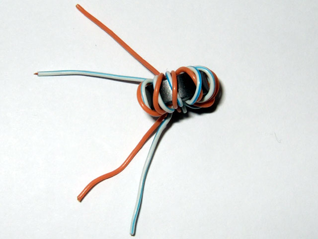
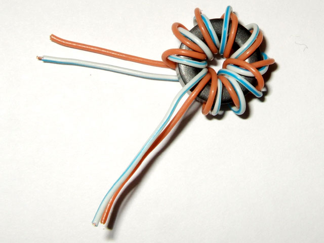
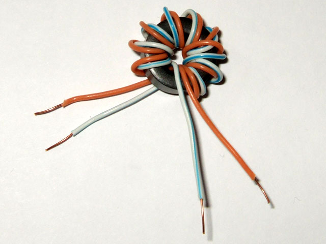
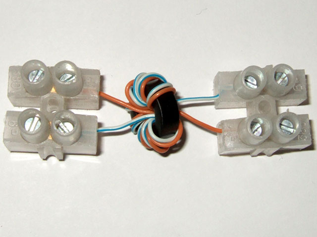 Connect one end of the wires into one side of a double piece of chock block, and the other into another.
Now you need to take a decision... If your line synchronises at over 4 Mbps, the chances are you might be using ADSL2+. ADSL2+ differs in that it uses frequencies on the telephone line up to 2.2 MHz, whereas ADSL and ADSL2 only use frequencies up to 1.1 MHz. There are three choices of filter:
- The 'mild' filter will allow all possible ADSL signals through including ADSL2+ and is suitable for all lines.
- The 'medium' filter will still allow ADSL2+ through but might cause some loss of connection speed (at the expense of greater reliability of course).
- The 'strong' filter will not allow ADSL2+ fully through as its frequency response begins to roll-off below 2 MHz and is therefore only suited if your line is running at speeds below 4 Mbps to start with.
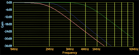
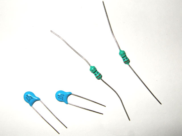 Each filter is made of two capacitors and two inductors. The table below shows which values you require, depending on your choice of filter.
| Filter | Capacitor | Inductor |
|---|---|---|
| mild | 470pF | 3.3uH |
| medium | 1nF | 4.7uH |
| strong | 1nF | 6.8uH |
Next take two of the inductors and a capacitor. On the opposite side of one of the chock blocks that has your choke connected, insert each of the inductors into one of the remaining holes and put the capacitor between the two holes. The other ends of the two inductors should now go into the final piece of chock block, and the remaining capacitor across the same chock block.
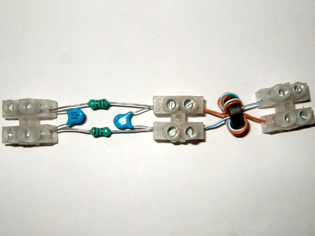 The results should look something like the picture on the right (if you haven't spotted it yet, you can click on the pictures to see a larger one).
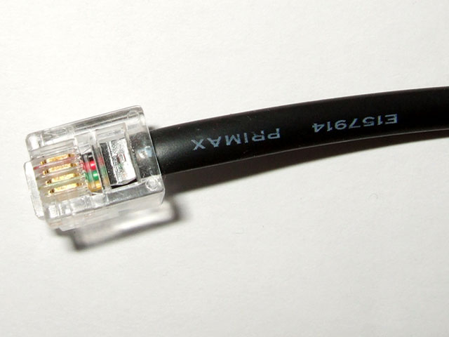
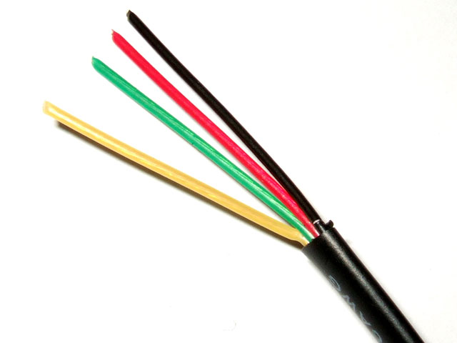
Finally, take the 'phone socket to ADSL box lead' that you have and cut it about 30cm from the end which goes into the ADSL modem. Strip back the shielding on both pieces, which will reveal some wires. If you have two wires, no more action is taken. If you find you have four wires, identify which are the middle two and cut off the outer ones (these aren't used). In the wire shown below the red and green wires are the inner two and the black and yellow wires can be disguarded.
Take one piece of the cable and insert the two wires into one end of your chock block construction - it doesn't matter which end. Then do the same with the remaining piece of wire, at the other end of your construction.
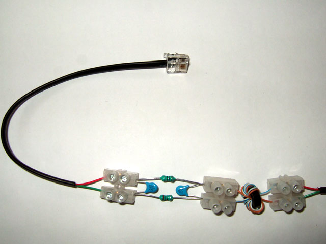
Bingo! You've finished. At this point it might be worth checking that there are no short-circuits. If you have a volt meter with a setting to measure resitance, check that:
- there is a connection between the two ends of the filter; and
- there are no short circuits across the chock blocks.
It's probably worth stating, just to be certain, that this is for ADSL connections (ie that which comes into your property on traditional copper telephone lines). It won't work with mobile broadband, cable broadband or satellite broadband!
Let us know how you get on and whether the WWADSL filter helps. Perhaps you might also like to share your construction experiences or tips with others too.
Wireless Waffle has talked extensively about pirate radio in the past, from short-wave music stations, to Brazilian sat-jackers. But it seems that, of all the nations on the planet, the Russians hold the baton for being the biggest pirates of them all.
This story begins when reading the latest intruder report from the IARU Region 1 Monitoring System. The report indicated that there had been an intrusion into the 80 metre amateur band between 3.5 and 3.6 MHz by Russian pirate stations running AM. Now historically the Voice of Korea (the North Korean broadcaster) has been transmitting in the 80 metre band (or the 75 metre band as it's called in in North America) on 3560 kHz in AM and the immediate assumption was that these new signals couldn't possibly be Russian pirates, but must be the Voice of Korea and perhaps a few other stations trying to jam it. The IARU report, however, says that the carriers are very unstable and that the modulation is voices in Russian.
 So the only thing to do to verify this story is to turn on a receiver and have a listen. Having done this, there were no obvious signals in the 80 metre amateur band. Having previous heard pirates just below the band at around 3450 kHz, the tuning dial was slowly rotated to ever lower frequencies. Nothing. And then, at 3175 kHz, something. A weak carrier... no, two carriers alternating... both rather unstable in frequency. Switching the receiver to AM yielded weak modulation. A bit more tuning, to 3125 kHz and a much stronger AM signal with a Russian voice and a wobbly carrier. Hey presto!
But what are these odd signals? Are they military operators in a private net (if so, why AM and why unencrypted)? Are they some kind of harmonics or intermodulation? Googling didn't bring much until a page on Sparky's Web Blog was found. It seems that these are effectively the equivalent of Russian CBers but presumably using much lower frequencies given the large distances between Russian cities. The band is known as the тройка band ('troika' in English which has several meanings from 'three of a kind' to a sledge or fairground ride). The band runs from approximately 2900 to 3200 kHz which are internationally allocated to the Aeronautical Mobile and Mobile services.
 There are aeronautical frequency assignments in the band (2872, 2899, 2921, 2962 and 3016 are frequencies assigned to North Atlantic traffic for example), but these lower frequencies are less often used unless propagation makes it totally necessary. Oddly, the various frequency lists for the band show very little aeronautical use in Russia (other than Irkutsk on 3016 kHz) - a coincidence? Probably the pirates know this and therefore feel free to mess about in the aviation bands, knowing that the Russian authorities are likely to be little interested in their activities.
If you're in Europe, when it gets dark (and lower frequency propagation opens up over the continent), why not give them a listen. It's fun to chase the carriers up and down in frequency. If you speak Russian, perhaps you could provide some translation as to what on earth they are talking about!
P.S. You might also want to take a listen to 2920 kHz USB as this seems to be a common calling channel for the more technically adept Russian pirates.
This story begins when reading the latest intruder report from the IARU Region 1 Monitoring System. The report indicated that there had been an intrusion into the 80 metre amateur band between 3.5 and 3.6 MHz by Russian pirate stations running AM. Now historically the Voice of Korea (the North Korean broadcaster) has been transmitting in the 80 metre band (or the 75 metre band as it's called in in North America) on 3560 kHz in AM and the immediate assumption was that these new signals couldn't possibly be Russian pirates, but must be the Voice of Korea and perhaps a few other stations trying to jam it. The IARU report, however, says that the carriers are very unstable and that the modulation is voices in Russian.
 So the only thing to do to verify this story is to turn on a receiver and have a listen. Having done this, there were no obvious signals in the 80 metre amateur band. Having previous heard pirates just below the band at around 3450 kHz, the tuning dial was slowly rotated to ever lower frequencies. Nothing. And then, at 3175 kHz, something. A weak carrier... no, two carriers alternating... both rather unstable in frequency. Switching the receiver to AM yielded weak modulation. A bit more tuning, to 3125 kHz and a much stronger AM signal with a Russian voice and a wobbly carrier. Hey presto!
But what are these odd signals? Are they military operators in a private net (if so, why AM and why unencrypted)? Are they some kind of harmonics or intermodulation? Googling didn't bring much until a page on Sparky's Web Blog was found. It seems that these are effectively the equivalent of Russian CBers but presumably using much lower frequencies given the large distances between Russian cities. The band is known as the тройка band ('troika' in English which has several meanings from 'three of a kind' to a sledge or fairground ride). The band runs from approximately 2900 to 3200 kHz which are internationally allocated to the Aeronautical Mobile and Mobile services.
 There are aeronautical frequency assignments in the band (2872, 2899, 2921, 2962 and 3016 are frequencies assigned to North Atlantic traffic for example), but these lower frequencies are less often used unless propagation makes it totally necessary. Oddly, the various frequency lists for the band show very little aeronautical use in Russia (other than Irkutsk on 3016 kHz) - a coincidence? Probably the pirates know this and therefore feel free to mess about in the aviation bands, knowing that the Russian authorities are likely to be little interested in their activities.
If you're in Europe, when it gets dark (and lower frequency propagation opens up over the continent), why not give them a listen. It's fun to chase the carriers up and down in frequency. If you speak Russian, perhaps you could provide some translation as to what on earth they are talking about!
P.S. You might also want to take a listen to 2920 kHz USB as this seems to be a common calling channel for the more technically adept Russian pirates.


